Exercise Q3.17
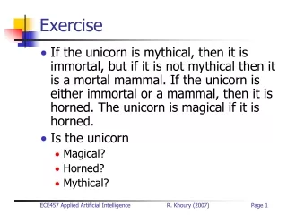
Exercise Q3.17. Design an FSM to keep track of the mood of four students working in the digital design lab. Each Student is either: 1. Happy (the circuit works) 2. Sad (the circuit blew up) 3. Busy (working on the circuit) 4. Clueless (confused about the circuit)

Exercise Q3.17
E N D
Presentation Transcript
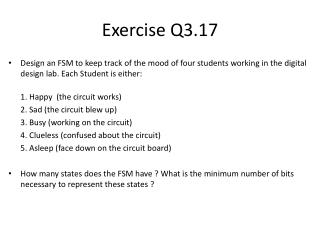
Exercise Q3.17 • Design an FSM to keep track of the mood of four students working in the digital design lab. Each Student is either: 1. Happy (the circuit works) 2. Sad (the circuit blew up) 3. Busy (working on the circuit) 4. Clueless (confused about the circuit) 5. Asleep (face down on the circuit board) • How many states does the FSM have ? What is the minimum number of bits necessary to represent these states ?
Exercise Q3.17 Solution • Each Student can either be: 1. Happy (the circuit works). 2. Sad (the circuit blew up). 3. Busy (working on the circuit). 4. Clueless (confused about the circuit). 5. Asleep (face down on the circuit board). • So each student can be in five different states. Hence, we can say that overall we have 625 distinct states (5 possible states for 4 students, 54 = 625). • For 625 distinct states, we need a minimum of ceiling(log2 625) = 10 bits.
Exercise Q3.22 • Design an FSM that recognizes 1101 or 1110. • Draw state transition diagram (use as few states as possible). • Choose state encodings. • Write state transition and output table using the encodings. • Write next state equations and output equations.
Exercise Q3.22 Solutuon 1 0 0 0 0 “ ” 0 “1” 0 “11” 0 “110” 0 “1101” 1 1 1 0 1 Reset 1 “111” 0 “1110” 1 0 1 1 0
State encoding: 1 0 0 0 0 “ ” 0 “1” 0 “11” 0 “110” 0 “1101” 1 1 1 0 1 Reset 1 “111” 0 “1110” 1 0 1 1 0 A = 000 ; B = 001 ; C = 010 ; D = 011; E = 100 ; F = 101 ; G = 110
K-Maps: S0+ S1+ S2+ S0 X S0 X S0 X 00 00 00 01 01 01 11 11 11 10 10 10 S2 S1 S2 S1 S2 S1 00 00 00 01 01 01 11 11 11 10 10 10 S0+ = S0’.S1.S2’ + X.S0’.S2’ + X.S0.S2 S1+ = X.S0.S1’.S2’ + X’.S0’.S1.S2’ + X.S0’.S1’.S2 + X’.S0.S2 F S0 X 00 01 S2 S1 00 01 11 10 S2+ = S0.S2 + X.S1 F = S0’.S2
Interview Q 3.1 (textbook)Design an FSM that recognizes 01010 when it is received serially. 1 0 1 1 0 “0101” ---- 0 “1” ---- 0 “0” ---- 0 “01” ---- 0 “010” ---- 0 0 1 1 0 Reset 0 “01010 ----- 1 0 1
Exercise Q3.27 (textbook) • Design an FSM with one input, A, and two outputs, X and Y. • X should be 1 if A has been 1 for at least three cycles altogether (not necessarily consecutively). • Y should be 1 if A has been 1 for at least two consecutive cycles. • Show your state transition diagram, encoded state transition table, next state and output equations, and schematic.
Important : Understand the problem correctly • X should be 1 if A has been 1 for at least three cycles altogether (not necessarily consecutively). • Y should be 1 if A has been 1 for at least two consecutive cycles. Sample Pattern1 (assuming Moore Machine, output is 1 cycle delayed) Input A 0 1 1 0 1 1 1 Output Y 0 0 0 1 1 1 1 Output X 0 0 0 0 0 1 1 Sample Pattern2 A 0 1 1 1 0 0 1 Y 0 0 0 1 1 1 1 X 0 0 0 0 1 1 1 Sample Pattern3 A 1 0 1 0 1 1 0 Y 0 0 0 0 0 0 1 X 0 0 0 0 0 1 1 Sample Pattern4 A 1 0 1 1 1 1 0 Y 0 0 0 0 1 1 1 X 0 0 0 0 1 1 1
0 Are there any equivalent states? Redundant/Equivalent states are those which can not be observed/distinguished from the FSM I/O behavior 0A ---- X = 0 Y = 0 0 1 1A ---- X = 0 Y = 0 0B ---- X = 0 Y = 0 0 0 1 2A ---- X = 0 Y = 0 1 1B ---- X = 0 Y = 0 0 0C ----- X = 0 Y = 1 0 1 +3A ---- X = 1 Y = 0 0 1 1 2B ---- X = 1 Y = 0 0 1C ----- X = 1 Y = 1 1 0 ― 1 +3B ---- X = 1 Y = 0 2C ----- X = 1 Y = 1 ― 1 +3C ----- X = 1 Y = 1 ―
0 0A ---- X = 0 Y = 0 Combining equivalent states 1c, 2c, 3c Reason : once these states are reached, output is always X=1, Y=1 for any input sequence. 0 1 1A ---- X = 0 Y = 0 0B ---- X = 0 Y = 0 0 0 1 2A ---- X = 0 Y = 0 1 1B ---- X = 0 Y = 0 0 0C ----- X = 0 Y = 1 0 1 +3A ---- X = 1 Y = 0 0 1 1 2B ---- X = 1 Y = 0 0 1C ----- X = 1 Y = 1 1 0 ― 1 +3B ---- X = 1 Y = 0 2C ----- X = 1 Y = 1 ― 1 +3C ----- X = 1 Y = 1 ―
Are there any more equivalent states? Explicit Equivalence: Two states are equivalent if outputs, Next states are identical for all input combinations. 0 0A ---- X = 0 Y = 0 0 1 1A ---- X = 0 Y = 0 0B ---- X = 0 Y = 0 0 0 1 2A ---- X = 0 Y = 0 1 1B ---- X = 0 Y = 0 0 0C ----- X = 0 Y = 1 0 1 +3A ---- X = 1 Y = 0 0 1 1 2B ---- X = 1 Y = 0 0 1C ----- X = 1 Y = 1 1 0 ― 1 +3B ---- X = 1 Y = 0 1
0 0A ---- X = 0 Y = 0 Combining equivalent states 2b, 3b Reason :Next states, outputs are identical for all input combinations. 0 1 1A ---- X = 0 Y = 0 0B ---- X = 0 Y = 0 0 0 1 2A ---- X = 0 Y = 0 1 1B ---- X = 0 Y = 0 0 0C ----- X = 0 Y = 1 0 1 +3A ---- X = 1 Y = 0 0 1 1 2B ---- X = 1 Y = 0 0 1C ----- X = 1 Y = 1 1 0 ― 1 +3B ---- X = 1 Y = 0 1
Common Mistake in Midterm2 • Many got B = C = F, but didn’t get E = G • Their state table looked like this. Explicit Equivalence E = G.
0 0A ---- X = 0 Y = 0 0 1 1A ---- X = 0 Y = 0 0B ---- X = 0 Y = 0 0 0 1 2A ---- X = 0 Y = 0 1 1B ---- X = 0 Y = 0 0 0C ----- X = 0 Y = 1 0 1 +3A ---- X = 1 Y = 0 0 1 1 2B ---- X = 1 Y = 0 0 1C ----- X = 1 Y = 1 1 ― 1
Another approach is to design an FSM for X (FSM-X) and a separate FSM for Y (FSM-Y) • Then “simulate” the execution from the “initial states”
VA ---- X = 0 FSM-X 0 0 FSM-Y SA ---- Y = 0 1 VB ---- X = 0 0 1 0 SB ---- Y = 0 1 VC ----- X = 0 0 1 1 SC ----- Y = 1 1 VD ----- X = 1 ― ―
0 VASA ---- X = 0 Y = 0 0 1 VBSA ---- X = 0 Y = 0 VBSB ---- X = 0 Y = 0 0 0 1 VCSA ---- X = 0 Y = 0 1 VCSB ---- X = 0 Y = 0 0 VCSC ----- X = 0 Y = 1 0 1 VDSA ---- X = 1 Y = 0 0 1 1 VDSB ---- X = 1 Y = 0 0 VDSC ----- X = 1 Y = 1 1 0 ― 1 VDSB ---- X = 1 Y = 0 VDSC ----- X = 1 Y = 1 ― 1 VDSC ----- X = 1 Y = 1 ―
0 VASA ---- X = 0 Y = 0 0 1 VBSA ---- X = 0 Y = 0 VBSB ---- X = 0 Y = 0 0 0 1 VCSA ---- X = 0 Y = 0 1 VCSB ---- X = 0 Y = 0 0 VCSC ----- X = 0 Y = 1 0 1 VDSA ---- X = 1 Y = 0 0 1 1 VDSB ---- X = 1 Y = 0 0 VDSC ----- X = 1 Y = 1 1 0 ― 1 VDSB ---- X = 1 Y = 0 VDSC ----- X = 1 Y = 1 ― 1 VDSC ----- X = 1 Y = 1 ―
0 VASA ---- X = 0 Y = 0 0 1 VBSA ---- X = 0 Y = 0 VBSB ---- X = 0 Y = 0 0 0 1 VCSA ---- X = 0 Y = 0 1 VCSB ---- X = 0 Y = 0 0 VCSC ----- X = 0 Y = 1 0 1 VDSA ---- X = 1 Y = 0 0 1 1 VDSB ---- X = 1 Y = 0 0 VDSC ----- X = 1 Y = 1 1 ― 1
Can also synthesize an FSM for X (FSM-X) and an FSM for Y (FSM-Y) separately (although this is different than what’s asked in this question)
VA ---- X = 0 FSM-X 0 0 FSM-Y SA ---- Y = 0 1 VB ---- X = 0 0 1 0 SB ---- Y = 0 1 VC ----- X = 0 0 1 1 SC ----- Y = 1 1 VD ----- X = 1 ― ―
State transition and output table, K-Maps for X, V1+, V0+ (for FSM-X) V1+ V0+ A A 0 0 1 1 V1 V0 V1 V0 00 00 01 01 11 11 10 10 Y V0 0 1 V1 0 1 Y = V1.V0 V0+ = V0.A’ + V1V0 + V0’.A V1+ = V1 + V0.A
Schematic for X, V1, V0 V1 DFF V1+ A X V0 DFF V0+
State transition and output table, K-Maps for Y, S1+, S0+ (for FSM-Y) S1+ S0+ A A 0 0 1 1 S1 S0 S1 S0 00 00 01 01 11 11 10 10 Y S0 0 1 S1 0 1 Y = S1 S0+ = A.S0’.S1’ S1+ = S1 + S0.A
Schematic for Y, S1, S0 S1 Y DFF S1+ A S0 DFF S0+
State transition and output table, K-Maps for Y, S1+, S0+ (for FSM-Y) : Using a different State Assignment for Sc. (Using 11 instead of 10) This helps in reducing the number of literals required to compute S0+. (requires 2 literals instead of 3) Efficient State Assignment problem is sometimes taken care of by EDA tools. S1+ S0+ A A 0 0 1 1 S1 S0 S1 S0 00 00 01 01 11 11 10 10 Y S0 0 1 S1 0 1 Y = S1 S1+ = S1 + S0.A S0+ = S1 + A
Can also directly implement using datapath (e.g. counters and shift registers) – all FF’s initialize to “0”. • One possible way is as given here. Other methods of implementations also exist. A 2 2 MUX 1 0 2 2-bit D-FFs “01” MUX 1 0 MUX 1 0 2 1 + FF FF 2 2-input AND (counts to 3 and remains at 3) (shifts to “11” and remains at “11”) X Y
![[Exercise Name] Functional Exercise](https://cdn0.slideserve.com/621913/exercise-name-functional-exercise-dt.jpg)

![[Exercise Name] Functional Exercise](https://cdn1.slideserve.com/1717560/exercise-name-functional-exercise-dt.jpg)


![[Exercise Name] Functional Exercise](https://cdn3.slideserve.com/6680259/exercise-name-functional-exercise-dt.jpg)
![[Exercise Name] Tabletop Exercise](https://cdn4.slideserve.com/9191716/exercise-name-tabletop-exercise-dt.jpg)