Download
1 / 16
160 likes | 239 Views
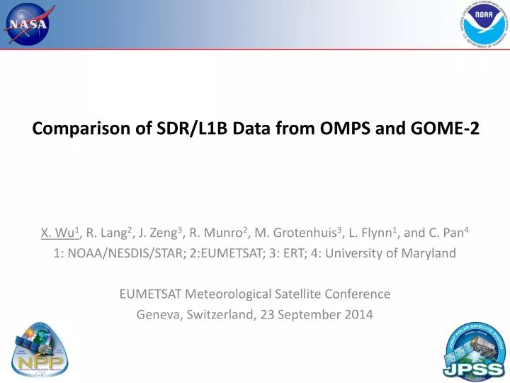
Comparison of SDR/L1B Data from OMPS and GOME-2. X. Wu 1 , R. Lang 2 , J. Zeng 3 , R. Munro 2 , M. Grotenhuis 3 , L. Flynn 1 , and C. Pan 4 1: NOAA/NESDIS/STAR; 2:EUMETSAT; 3: ERT; 4: University of Maryland EUMETSAT Meteorological Satellite Conference Geneva, Switzerland, 23 September 2014.

E N D
Comparison of SDR/L1B Data from OMPS and GOME-2 X. Wu1, R. Lang2, J. Zeng3, R. Munro2, M. Grotenhuis3, L. Flynn1, and C. Pan4 1: NOAA/NESDIS/STAR; 2:EUMETSAT; 3: ERT; 4: University of Maryland EUMETSAT Meteorological Satellite Conference Geneva, Switzerland, 23 September 2014
Motivation (1/2) • The Ozone Mapper Profiler Suite (OMPS) was launched onboard the U.S. Suomi National Polar-orbiting Partnership (S-NPP) in October 2011. • Will be a payload in future Joint Polar Satellite System (JPSS). • The second generation of the Global Ozone Monitoring Experiment (GOME-2) instruments were launched onboard the European METOP-A in October 2006 and METOP-B in September 2012. • Will also be carried on METOP-C • Tow series of sophisticate instruments for the remote sensing of ozone, each for ~two decades. • Nearly concurrent – unique opportunity e.g. some OMPS may overlap with three GOME-2 and vice versa. • Interested in their long term comparison.
Motivation (2/2) Signal Instrument Instrument Performance Monitoring SDR Validation EDR Validation SDR, or Level 1B Courtesy Google, Weng et al, Wu et al. and Pan et al. EDR (Ozone, aerosol, SO2)
OMPS & GOME-2 Calibration • The key product for both instruments is the ratio of the back scattered UV radiance to the incoming solar radiance. • Both instruments regularly sense solar irradiance reflected from a Solar Diffuser (SD) such that instrument degradation is self-corrected, as long as the SD is stable. • OMPS maintains SD stability with a Reference Diffuser. • The Spectral Line Source (SLS) on GOME-2A for the same purpose did not work as expected on orbit. • OMPS has been exceptionally stable. • Working SD has degraded slightly. • Shortwave channels degradation became certain only recently. • GOME-2 (esp. METOP-A): up to ~10% degradation due to SD. • Will be corrected in Level 1C.
Simultaneous Nadir Overpass (SNO) • No compensation for size, shape, and orientation of FOV’s : • Scene (ozone distribution) is often sufficiently uniform. • Caution: SZA variation within the scene, esp. NP.
SNO Results with METOP-A/B Solar Earth View Reflectance Metop-B Metop-A
Simultaneous Nadir Overpass (SNO) • No compensation for size, shape, and orientation of FOV’s : • Scene (ozone distribution) is often sufficiently uniform. • Caution: SZA variation within the scene, esp. NP.
Time Series of SNO Stray Light Correction NM Day 1 Solar Degradation rate vs. orbit life and λ. Unknown fluctuations. Known events.
Chasing Orbit – Method (1/2) Ground track of S-NPP orbit (blue) is chasing that of NOAA-19 (green)
Chasing Orbit – NM Stray Light Correction
Chasing Orbit – NP NP Day 1 Solar Correction SAA Dark
Stable Earth Target – Tropical Pacific • Assume that reflectance from clear ocean is invariant. • 20S - 20N, 100W - 180W. • Plenty clear scenes. • Stable ozone content. • Low aerosols. • Use “minimum reflectance” to identify clear scenes: • Account for Raleigh scattering. • Select the reflectance in the darkest 1st percentile.
Stability – method Using spectral radiance to identify clear pixels. Spectral reflectance with and without consideration of Rayleigh scattering variation with solar irradiance.
Stability – results OOB Stray Light Correction Also did similar (but separately) over Libyan Desert. It seems that UV radiance is scattering limited so the underlying surface doesn’t matter. The aerosols do, however. Day 1 Solar update
Summary • Instead of calibrating one instrument using the “better” one as reference, comparison may work as long as errors (random, systematic, operational) in either instrument are not correlated. • This is often the case and can help to understand the characteristics and operations of both, e.g., deficiencies in both OMPS and GOME-2, mostly confirm and quantify but some were unknown.. • Furthermore, it would be beneficial to also compare with common references (stable earth target, other ozone instruments), in addition to direct comparison of each other. • Important to continue in long term for climate applications. • Coordinate through the newly formed UV Subgroup of the Global Space-based Inter-Calibration System (GSICS) Research Working Group (GRWG).