Unit-4 1401
Unit-4 1401. AERODROME DATA, PHYSICAL CHARACTERISTICS AND OBSTACLE RESTRICTION. Syllabus. Aerodrome data - Basic terminology – Aerodrome reference code – Aerodrome reference point – Aerodrome elevation – Aerodrome reference temperature

Unit-4 1401
E N D
Presentation Transcript
Unit-41401 AERODROME DATA, PHYSICAL CHARACTERISTICS AND OBSTACLE RESTRICTION
Syllabus • Aerodrome data - Basic terminology – Aerodrome reference code – Aerodrome reference point – Aerodrome elevation – Aerodrome reference temperature • Instrument runway, physical Characteristics; length of primary / secondary runway – Width of runways – Minimum distance between parallel runways etc. – obstacles restriction.
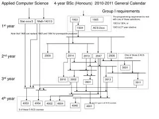
Key Topics • Design of an Aerodrome • Classification of Aerodromes in India • Types of Runway • Design of Length of Runway
Types of Aerodromes in India • International Aerodrome-13 • Domestic aerodrome-68 domestic terminals • Military Aerodrome-Pathankot • Custom Aerodrome-Madurai
Chennai Aerodrome parameter • Location Trisoolam;MSL=16m • Bearing=12*59’N 80*E • Runway 1. 07/25; 3.658m Asphalt • Runway 2.12/30; 2.05m Asphalt/Concrete
Aerodrome Data Aerodrome Ref Point, Aerodrome Chart
Aerodrome Data • Contain Aerodrome Chart • Aerodrome location giving-name, lat and long, airport elevation physical location, distance & bearings-34 ft AMSL; 12*59’37” N, 01*08’37”E • Aerdrome Administration-name, number, fax of the operator -AAI • Movement Areas like Runways, Taxiways, Aprons • Visual Aids-marking and lighting system for airports,Visual Approach Slope Indicator and Navigational Aids • Ground Services like Fuel, communication from Ground to Pilot
Typical Example • Name of Aerodrome-Chennai or Delhi etc & National Airport or International as NAT/INT • Runway Number from 01 to 36 & No. of Runways as 1 or 2 and their designation and length as 07/25; 3.658mile • Elevation of Runway • Type of Traffic ( IFR/VFR) • Location of Wind Sox (illuminated and non illuminated) • Location of Aerodrome Ref point, Control Tower, Terminal Building, Fire Station, Nav.
AERODROME CHART • Layout of runways, taxiways and apron(s); b) type of the runway surfaces; c) designations and length of runways; RWY NR-18; 2286M d) designations of the taxiways e) location of illuminated and non- illuminated wind direction indicators; • Location of the aerodrome reference point • Location of terminal buildings • Location of control tower • Location of fire station • Location of navigation aids • Location of isolation bay • Location of helipads
Runway Details • Designation: RWY NR-18 • Bearing:184*20’ GEO and 184*15’ • Runway Size :2286 x 45 m • Width :< 30m, usually 45m, based on the wingspace of aircraft • Separation between Parallel Runway <1300m • Slope of Runway < 5% • Permissible Cross Wind = 20 Knots • Runway Surface : Loss Free and Friction Free • Material : Partly Asphalt and partly concrete
ARP-Aerodrome Ref Point • ARP defined as geometrical centre of runway, and height decided by the AAI & Point-ARP-the magnetic variation given to the nearest degree from magnetic north of the runway - Indicated as ARPlat and ARPlong
ARP-Chennai • Elevation 34 ft AMSL • Latitude 125937 N • Longitude 010837E • Land Area 1400 Acres
RUNWAY TORA & TODA,Characterestics, types and secondary runway – Width of runways – Minimum distance between parallel runways etc. – obstacles restriction
TORA & TODA • Take off Run-TORA =Length of runway declared available and distance traversed on ground run of an airplane taking off = 1.15 x Midpoint length of runway) • Take off Distance-TODA-length of the takeoff run available plus the length of Clear way; TODA=TORA + Clearway or 1.5 Tora
Runway Length • Depends on the type of aircraft and speed of landing( Airbus require 3.5Km) • 1800m for weights< 90,000Kg for smaller aircrafts • ,2400m For Widebodies aircrafts • 4000m for International flights
Runway Visual Range-RVR • Is an instrumentally derived value that representing the horizontal distance a pilot can see down the runway, determined by visibility sensors • RVR measured in increments of 100 feet up to 1,000 feet, increments of 200 feet from 1,000 feet to 3,000 feet, and increments of 500 feet above 3,000 feet to 6,000 feet.
Types • Single Runway-Simplest Runway used when winds blow on the Runway and suitable when peak HR traffic is <50 operations; Both ends can be used when the winds are light for landing and departure. • Parallel Runway-when winds blow on the runway and peak hr.traffic >50 operations and landing and departure on two runways • Intersecting Runway-when wind blow in one direction is > the other, intersecting runway being used. • Open V & Closed V runway
Single and Parallel Runways Single Runway Layout Equal Dep & ARR Terminal Building Parallel Runway L/TO L/TO
VFR,IFR Runway( Precision and Non precision) • Visual Runway • Instrument Runway a.Precision Runway-marked at edge with white painting-guidance both for vertical and horizontal b.Non Precision Instrument ( no vertical guidance, only horizontal guidance)
Instrument runway-Features • Marking and lighting systems for runways; • b) approach lighting system; • c) visual approach slope indicator system; • d) aerodrome beacon; • e) marking and lighting systems for taxiways; and • f) any other marking and lighting systems.
Parallel Runway-9R-9L N 0 270 90 180
Designated positions in the runway • Position 1. Aircraft initiates call to taxi for departing flight. Runway from Apron • Position 2. Departing aircraft held at position 2. Engine run-up be performed here. • Position 3. Take-off clearance issued • Position 4. Clearance to land is issued • Position 5. Clearance to taxi to apron • Position 6. Parking information issued
Parallel Runways <4300’ • Parallel Runways <4300’, Aircraft still required to be 2.5 NM apart on the same localizer, • but close as 1.5 NM apart diagonally between the localizers
Minimum distance between parallel runways • Safe if the runway spacing is greater than 1270m Unsafe if the spacing is lower than 930 m.
Parallel Runway Approaches (4) • Close Parallel • Independent parallel approaches • Independent Close Parallel • Independent Close Parallel with Cross Wind Close parallel.
Width of runways • Runway Width =45 Meters based on Airworthiness requirements for AB 380