Download
1 / 11
110 likes | 284 Views
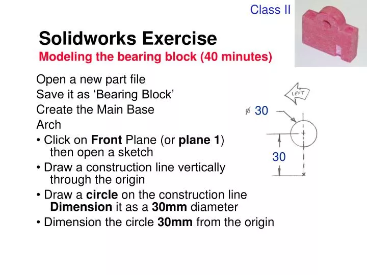
Class II. Solidworks Exercise Modeling the bearing block (40 minutes). Open a new part file Save it as ‘Bearing Block’ Create the Main Base Arch • Click on Front Plane (or plane 1 ) then open a sketch • Draw a construction line vertically through the origin

E N D
Class II Solidworks ExerciseModeling the bearing block (40 minutes) • Open a new part file • Save it as ‘Bearing Block’ • Create the Main Base • Arch • • Click on Front Plane (or plane 1) then open a sketch • • Draw a construction line vertically through the origin • • Draw a circle on the construction line Dimension it as a 30mm diameter • • Dimension the circle 30mm from the origin 30 30
Solidworks ExerciseModeling the bearing block (40 minutes) • Create the Main Base • Rectangle • • Draw a line snapped from the right quadrant of the circle to the right. • • Connect another line from the end point and down, snapped even with the origin • • Connect a third line from this endpoint to the origin (after the third line, click the right mouse select end chain).
Solidworks ExerciseModeling the bearing block (40 minutes) • Create the Main Base • Mirror • • Holding down Ctrl, highlight the construction line and the three lines you just drew. • • Hit the Mirror tool, or Tools, Sketch Tools, Mirror. • • Dimension the overall width to 60mm. 60
Solidworks ExerciseModeling the bearing block (40 minutes) • Create the main base • Trim • • Click Trim(or tools sketch tools trim) and select the bottom half of the circle. Click to delete a quarter of the circle. • • Repeat process to remove the other quarter of the circle
Solidworks ExerciseModeling the bearing block (40 minutes) • Make the main base • Hole • • Draw a circle anywhere and dimension it to 10mm • • Using Add Relations, make it concentric with the top arch 10
Solidworks ExerciseModeling the bearing block (40 minutes) • Make the main base • • Hit the Extrusion key • • Make End Condition Blind; and type in 15mm for distance • ª Click OK and label this Mainbase.
Solidworks ExerciseModeling the bearing block (40 minutes) • Make cbore • • Go to isometric view and highlight a flat area on top of the part, then open a sketch on the plane shown. • • Draw a circle anywhere and dimension it to 8mm. • • Dimension it 7.5mm from both edges. • • Extrude Cut this sketch to 5mm • • Label this Cbore 8
Solidworks ExerciseModeling the bearing block (40 minutes) • Make the thru hole • • Select the plane at the bottom of the cbore and open a sketch • • Draw a circle anywhere and make it 5mm diameter • • Use Add Relations to make this concentric to the cbore edge. • • Extrude Cut a hole through all • • Label thisHole
Solidworks ExerciseModeling the bearing block (40 minutes) • Mirror the hole • • Select Insert, Pattern/Mirror, Mirror Feature • • Under Mirror Plane, select Right plane (or plane 3) in the feature manager; under Features to Mirror, choose Cbore and Hole in the feature manager • • Leave this called Mirror1
Solidworks ExerciseModeling the bearing block (40 minutes) 15 • Make a notch • • Open a sketch on the Top plane (or plane 2) • • Draw a circle centered on the bottom edge of the part • • Dimension the circle at 6mm. Dimension the circle 15mm to the right of the origin (select the origin in the feature manager) • • Select the Extrude Cut feature, and select a Blind cut of 15mm • • Select OK and label this Notch 6
Solidworks ExerciseModeling the bearing block (40 minutes) • Cut top of notch • • Rotate the part until you can see the end face of the previous cut • • Select this plane and open a sketch • • Select the entire half-circle face and select ConvertEntities • • Draw a constructionline through the straight part of this half circle (parallel to the edge of the bearing block • • Select Revolve Cut Feature, and rotate 90 degrees • • Click OK and name this Notch Top