Download
1 / 30
300 likes | 921 Views
Remote Sensing of Tropospheric Aerosols from Space: Past, Present, and Future. Michael D. King, 1 Yoram J. Kaufman, 1 Didier Tanré 2 and Teruyuki Nakajima 3 1 NASA Goddard Space Flight Center, Greenbelt, MD USA 2 Université des Sciences des Techniques de Lille, Villeneuve d’Ascq, France

E N D
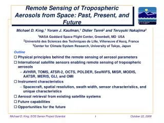
Remote Sensing of Tropospheric Aerosols from Space: Past, Present, and Future Michael D. King,1 Yoram J. Kaufman,1 Didier Tanré2 and Teruyuki Nakajima3 1NASA Goddard Space Flight Center, Greenbelt, MD USA 2Université des Sciences des Techniques de Lille, Villeneuve d’Ascq, France 3Center for Climate System Research, University of Tokyo, Japan Outline • Physical principles behind the remote sensing of aerosol parameters • International satellite sensors enabling remote sensing of tropospheric aerosols • AVHRR, TOMS, ATSR-2, OCTS, POLDER, SeaWiFS, MISR, MODIS, AATSR, MERIS, GLI, and OMI • Instrument characteristics • Spacecraft, spatial resolution, swath width, sensor characteristics, and unique characteristics • Aerosol retrieval from existing satellite systems • Future capabilities • Opportunities for the future
Reflection Function as a Function of Aerosol Optical Thickness • The reflection function is given by R(ta, w0; µ, µ0, f) = • The greatest sensitivity of reflected solar radiation to aerosol optical thickness occurs when • the surface reflectance is small • the single scattering albedo is large (small absorption) • larger slant angles (µ < 1) pI(0, –µ, f) µ0F0
MISR Provides New Angle on Haze • In this MISR view spanning from Lake Ontario to Georgia, the increasingly oblique view angles reveal a pall of haze over the Appalachian Mountains
Aerosol Properties • Eight MODIS bands are utilized to derive aerosol properties • 0.47, 0.55, 0.65, 0.86, 1.24, 1.64, 2.13, and 3.75 µm • Ocean • reflectance contrast between cloud-free atmosphere and ocean reflectance (dark) • aerosol optical thickness (0.47-2.13 µm) • size distribution characteristics (ratio between the assumed two log-normal modes, and the mean size of each mode) • Land • dense dark vegetation and semi-arid regions determined where aerosol is most transparent (2.13 and 3.75 µm) • contrast between Earth-atmosphere reflectance and that for dense dark vegetation surface (0.47 and 0.66 µm) • enhanced reflectance and reduced contrast over bright surfaces (post-launch) • aerosol optical thickness (0.47 and 0.66 µm)
Aerosol Effects on Reflected Solar Radiation over Land Biomass burning Cuiabá, Brazil (August 25, 1995) 10 km q0 = 36° R = 0.66 µm G = 0.55 µm B = 0.47 µm R = 1.65 µm G = 1.2 µm B = 2.1 µm 20 km
Surface Reflectance at Near-Infrared Wavelengths • Surface reflectance is high at 2.2 µm, moderate at 0.66 µm, and low at 0.49 µm • The aerosol effect on reflected solar radiation is small at 2.2 µm and large at 0.49 µm • MODIS operational algorithm over land assumes Kaufman et al. (1997) Ag(0.47 µm) = 0.5Ag(0.66 µm) = 0.25Ag(2.1 µm)
Dynamic Aerosol Models Remer et al. (1996) • Accumulation mode particles (r < 0.3 µm) of mostly organic smoke particles or sulfates depend on optical thickness • Aerosol-free troposphere plus stratospheric aerosol (0.3 µm < r < 0.8 µm) • Maritime salt particles in the mid-Atlantic region (0.8 µm < r < 2.5 µm) • Coarse particles (r > 2.5 µm)
Techniques for Remote Sensing of Tropospheric Aerosol from Space
Techniques for Remote Sensing of Tropospheric Aerosol from Space
Aerosol Properties Land Ocean Land-Ocean Cloud Mask Polarization Polarization-Ocean Polarization-Land-Ocean Not Used for Aerosols Hyperspectral AVHRR TOMS ATSR-2/AATSR OCTS POLDER SeaWiFS MISR MODIS MERIS GLI OMI 1.0 0.8 0.6 Transmission 0.4 0.2 0.0 0.3 0.4 0.5 0.6 0.7 0.8 0.9 1.0 Wavelength (µm)
Aerosol Properties Near-infrared and thermal infrared Land Ocean Land-Ocean Cloud Mask Not Used for Aerosols AVHRR ATSR-2/AATSR OCTS MODIS GLI 1.0 0.8 0.6 Transmission 0.4 0.2 0.0 1.0 1.5 2.0 3.0 4.0 6.0 10.0 20.0 15.0 Wavelength (µm)
Tropospheric Aerosol Data Record 1987 2002 1981 1983 1984 1986 1989 1990 1992 1993 1995 1996 1998 1999 2001 2004 1982 1985 1988 1991 1994 1997 2000 2003 InstrumentSpacecraft AVHRR NOAA-7, 9, 11, 14, L, Metop-1 TOMS Nimbus-7, Meteor, EP, ADEOS, QuikTOMS ATSR-2 ERS-2 OCTS ADEOS POLDER ADEOS ADEOS II SeaWiFS OrbView-2 MISR Terra MODIS Terra Aqua USA Europe Japan
Tropospheric Aerosol Data Record 1987 2002 1981 1983 1984 1986 1989 1990 1992 1993 1995 1996 1998 1999 2001 2004 1982 1985 1988 1991 1994 1997 2000 2003 InstrumentSpacecraft AATSR Envisat-1 MERIS Envisat-1 GLI ADEOS II OMI Aura USA Europe Japan
Aerosol Optical Thickness AVHRR April 1997 No Data 0.0 0.1 0.2 0.3 0.4 0.5 Aerosol Optical Thickness (0.63 µm)
Aerosol Optical Thickness TOMS April 1997 No Data 0.0 0.1 0.2 0.3 0.4 0.5 0.6 0.7 0.8 0.9 1.0 Aerosol Optical Thickness (0.38 µm)
Radiance and Polarization Measurements from POLDER R = 0.865 µm G = 0.670 µm B = 0.443 µm Western Europe March 10, 1997 Polarization Radiance
Aerosol Optical Thickness POLDER April 1997 No Data 0.0 0.1 0.2 0.3 0.4 0.5 Aerosol Optical Thickness (0.865 µm)
Ångström Exponent POLDER April 1997 No Retrieval No Data 0.0 0.1 0.2 0.3 0.4 0.5 0.6 0.7 0.8 0.9 1.0 Angstrom Exponent
Aerosol Optical Thickness OCTS April 1997 No Data 0.0 0.1 0.2 0.3 0.4 0.5 Aerosol Optical Thickness (0.500 µm)
Ångström Exponent OCTS April 1997 No Retrieval No Data 0.0 0.1 0.2 0.3 0.4 0.5 0.6 0.7 0.8 0.9 1.0 Angstrom Exponent
Aerosol Optical Thickness MODIS April 19, 2000
Aerosol Optical Thickness 0 20 40 60 80 100 Fraction of Aerosol Retrievals for 150 days
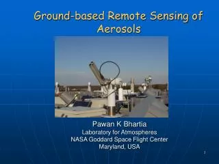
Global Distribution of AERONET Stations—August 2000 • Automatic recording and transmitting Sun/Sky Photometers • Data Base: Aerosol optical thickness, size distribution, phase function & precipitable water • Collaborative: NASA – instruments/sites and centralized calibration & database • Non-NASA – instruments/sites
TARFOX Atlantic Ocean (July 1996) 0.6 0.5 0.4 0.3 Retrieved optical thickness 0.2 0.1 l = 0.55 µm 0.0 0.0 0.1 0.2 0.3 0.4 0.5 0.6 Sunphotometer optical thickness 0.0
SCAR-B Brazil (August-September 1995) 2.5 Forest 2.0 1.5 Retrieved optical thickness 1.0 Cerrado 0.5 l = 0.66 µm 0.0 0.0 0.5 1.0 1.5 2.0 2.5 Sunphotometer optical thickness
Summary and Conclusions • Tropospheric aerosols have been ‘rediscovered’ as a major influence on the radiation balance of the Earth, with a potentially large mitigating influence on greenhouse forcing • In the past we have been largely forced to use uncalibrated sensors or wide field-of-view ultraviolet spectrometers not specifically designed for the remote sensing of tropospheric aerosol properties • Since 1996, with the launch of OCTS and POLDER on ADEOS, we have entered a new era of quantitative remote sensing of tropospheric aerosol from space • With the launch of EOS, Envisat-1, and ADEOS II, we will have an unprecedented array of spaceborne sensors with unique characteristics that will enable quantitative aerosol observations on a global scale • Enhanced onboard calibration • Use of deep space and lunar maneuvers for calibration and sensor degradation analysis • Vigorous vicarious calibration using ground-based and airborne sensors • Narrow spectral bands that avoid molecular absorption bands • Multispectral and multiangle observations • Polarization
Summary and Conclusions • These spaceborne sensors, when coupled with the AERONET network of sun/sky radiometers for the validation of satellite data, derivation of aerosol models, and statistical characterization of aerosol in remote pristine environments, should enable a much improved analysis of aerosol forcing of the Earth-atmosphere-ocean system • The next advance from space is monostatic lidar that will make it possible to characterize the vertical distribution of tropospheric aerosols and clouds that, when coupled with multispectral and multiangular radiometry, will advance the state of our knowledge of how aerosols interact with the Earth and its atmosphere • GLAS (December 2001) • PICASSO-CENA (February 2003)