
Comprehensive Guide to UML Diagrams: Types & Usage
E N D
Presentation Transcript
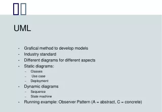
Components of the UML • Class Diagram • Object Diagram • Use Case Diagram • State Diagram • Sequence Diagram • Activity Diagram • Collaboration Diagram • Component Diagram • Deployment Diagram
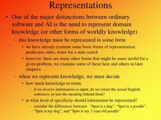
The Use Case Diagram • It contains use cases and actors, illustrating the relationships between the two sets. • These diagrams are usually the starting point of the analysis phase when designing a system. • Use cases show the overall structure and availability in a system to non-technical readers such as management and end users.
A use case consists of: • A System that performs a function. A system has defined boundaries and can be broken down into sub-systems. Microsoft Visio use case diagram for a system is shown below.
A use case consists of (contd.) • An Actor(s) is used to represent something that uses a system. An actor can be a person or another system. Microsoft Visio uses following diagram to represent an actor.
A Use Case Consists of • Use cases which represent actions that a user takes on a system. Use cases are represented by an ellipse. Following diagram represents a use case diagram for a developer developing software.
The Use Case Diagram Use Case (How to use the system And its behavior) Actors System (humans or external Systems)
The Class and Object Diagrams • A class diagram is used to represent different classes, their relationship to each other, and which subsystem they belong to. • Object diagram shows instances of classes. • Class diagram is more generic and object diagram is more specific.
Class and Object Diagrams Class Diagram Object Diagrams
Activity Diagram • The activity diagram is used to analyze the behavior within more complex use cases and show their interaction with each other. Activity diagrams are used early in the system’s development process and are usually used to represent more complicated business activities.
An Activity Diagram with a Fork and a Join for a parallel process
The Sequence Diagram • The sequence diagram is used to show interaction between actors and objects and other objects. Messages are sent from actor to object, object to object and object to actor to show the flow of control through a system. Sequence diagrams are use to realize use cases by documenting how a use case is solved with the current design of the system.
Sequence Diagrams Time
The Sequence • The GUI notifies the operating system about the keystroke. • The operating system notifies the CPU. • The CPU sends a message to the monitor. • The monitor presents the alphanumeric character on screen, providing visual feed back to the user.
The Connections in Sequence Diagrams Asynchronous Connection (The actor can Continue to work while action is taken by the System) Synchronous Connection (The actor has to wait for system approval) Simple Message (Transfers control from one object to another )
Statechart diagrams • Statechart diagrams look similar to activity diagrams and are sometimes confusing. An activity diagram is used to model how different areas of work behave with each other and interact, a statechart diagram is used to represent a single object and how its behavior causes it to change state.
The State Diagram • Class and Object diagrams model system statically. • State Diagram represent the dynamic behavior/flow of the system. • State diagrams are used between systems analysis and design phase.
UML Symbols for State Diagram End Point Initial Starting Point
Collaboration Diagram • Collaboration diagrams are used to bring class diagrams to the next step. They represent the interaction and the relationships between the objects created in earlier steps of the domain modeling process. • Collaboration diagrams are often drawn between class and sequence diagrams.
Component Diagrams • Component diagrams model software components and their relationships with each other. • A component is a single piece of software. It can be a file, product, executable, script or so on.
Deployment Diagrams • Deployment diagrams are used to model hardware as it relates to the deployment of the system that you are modeling in UML. • A deployment diagram has only two major pieces of its notation, the node and the communication association.
A deployment diagram The diagram illustrates that a Web Server interacts with a ClientPC via an HTTP protocol, and the ClientPC communicates with a printer via a USB protocol.
Credits/Further Reading • Some Information was taken and modified from UML: A Beginners Guide by Jason T. Roff, McGraw Hill.