Download
1 / 23
240 likes | 289 Views
Explore the development and importance of HTS filters in rejecting RFI for radio astronomy. Discover the process, filter examples, and next steps to enhance radio telescope performance.

E N D
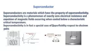
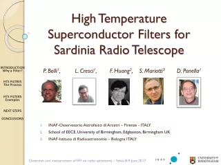
High Temperature Superconductor Filters for Sardinia Radio Telescope P. Bolli1, L. Cresci1, F. Huang2, S. Mariotti3 D. Panella1 INTRODUCTIONWhy a Filter? HTS FILTRESThe Process HTS FILTERSExamples NEXT STEPS CONCLUSIONS INAF-Osservatorio Astrofisico di Arcetri – Firenze - ITALY School of EECE, University of Birmingham, Edgbaston, BirminghamUK INAF-Istituto di Radioastronomia – Bologna ITALY Detection and measurement of RFI on radio astronomy – Yebes 8-9 June 2017
WHY A FILTER ? Given a radio receiver chain, in order to reject RFI, a band pass filter and/or a notch may be placed just after LNA. After LNA with typical Gain 35…40 dB, the increase of Tsys is negligible. INTRODUCTIONWhy a Filter? HTS FILTRESThe Process HTS FILTERSExamples NEXT STEPS CONCLUSIONS Usually RFI became dangerous for receiver linearity at the end of the chain (mixer, IF Amp, final stage). RFI is every time blinding, but if linearity will be affected, even the software mitigation will fails. So, why a front-end filter? Detection and measurement of RFI on radio astronomy – Yebes 8-9 June 2017
WHY A FILTER ? The new frontier of RA calls for large bandwidth (1octave) or very large, as the case of BRAND-EVN ( 1 decade). INTRODUCTIONWhy a Filter? HTS FILTRESThe Process HTS FILTERSExamples NEXT STEPS CONCLUSIONS • For many years, usual and common LNA had a Po1~+5 dBm.An emerging brand sells excellent LNA but with Po1~ -12 dBm (C-band) • Given this conditions, if radar(s) or strong source(s) are located near the Radiotelescope, the risk of non linearity distortion will affect the LNA too. • For this reasons a front-end filter may help Detection and measurement of RFI on radio astronomy – Yebes 8-9 June 2017
FILTER REQUIREMENTS The loss of the filter must not increase significantly the Noise Temperature. INTRODUCTIONWhy a Filter? HTS FILTRESThe Process HTS FILTERSExamples NEXT STEPS CONCLUSIONS This mean the loss and the mismatch of the filter should be the lower as possible and Tsys still remain competitive. |s21| and |s12| : the lowest possible|s11| and |s22| : the lowest possible Detection and measurement of RFI on radio astronomy – Yebes 8-9 June 2017
ON THE FILTER LOSS Due to the extremely low loss, HTS Filter has been used as narrow bandFilters. For such applications the low loss performances cannot be overcome. HTS Filters appeared immediately as the best technological solution. INTRODUCTIONWhy a Filter? HTS FILTRESThe Process HTS FILTERSExamples NEXT STEPS CONCLUSIONS Even more, with wide band, we expect an extremely low loss. LF (intedigital, 20K) ≈ 0.4 @ P BandLF (HTS, 20K) ≈ 0.04 @ P Band (due to MgO substrate – estimated value) Detection and measurement of RFI on radio astronomy – Yebes 8-9 June 2017
THE FILTER Filter Design HTS furnisher INTRODUCTIONWhy a Filter? HTS FILTRESThe Process HTS FILTERSExamples NEXT STEPS CONCLUSIONS Ti alloy Milling Layout Optimization Ti alloy house drawing Assembly and Test & measurement Ti alloy plating Detection and measurement of RFI on radio astronomy – Yebes 8-9 June 2017
HST STRUCTURE Ion Beam Milling GOLD 0.2 mm HTS (YBCO) 0.6 mm INTRODUCTIONWhy a Filter? HTS FILTRESThe Process HTS FILTERSExamples NEXT STEPS CONCLUSIONS MgO Dielectric 500 mm HTS (YBCO) 0.6 mm GOLD 0.2 mm Detection and measurement of RFI on radio astronomy – Yebes 8-9 June 2017
HST DESIGN INTRODUCTIONWhy a Filter? HTS FILTRESThe Process HTS FILTERSExamples NEXT STEPS CONCLUSIONS The filter may be band pass, low pass, high pass, notch or a combination of them The synthesis is based on original circuital solutions and layout geometry coming from the long experience of Lancaster’s group at Birmingham University. More deeply, the design method is based on coupling coefficients of intercoupled resonators and the external quality factors of the input and output resonators. Later , the geometry is fine tuned and analysed with Sonnet EM simulator Detection and measurement of RFI on radio astronomy – Yebes 8-9 June 2017
HST DESIGN The housing should firmly host the PCB. Excellent electrical contacts on both central pin and GND is required The mechanical design must be robust against differential of Coeff. Of Thermal Expansion INTRODUCTIONWhy a Filter? HTS FILTRESThe Process HTS FILTERSExamples NEXT STEPS CONCLUSIONS Ti6 Al4 V is the alloy that match the CTE of MgO, both at room temperature and in cryogenic environment. In order to better match the CTE, a “gummous” epoxy is used.The HenkekAblefilm5025E – 4 mils is an electrical conductive, gommous, double-sided adhesive tape. Detection and measurement of RFI on radio astronomy – Yebes 8-9 June 2017
HST: ASSEMLING PHASE INTRODUCTIONWhy a Filter? HTS FILTRESThe Process HTS FILTERSExamples NEXT STEPS CONCLUSIONS HTS C-Band : Assembling phase Detection and measurement of RFI on radio astronomy – Yebes 8-9 June 2017
HST TEST & MEASUREMENT Test & Measurement were made in parallel in two laboratories, Florence and Bologna INTRODUCTIONWhy a Filter? HTS FILTRESThe Process HTS FILTERSExamples NEXT STEPS CONCLUSIONS Detection and measurement of RFI on radio astronomy – Yebes 8-9 June 2017
T&M of FILTERS Cavity filter tested on liq. N2 INTRODUCTIONWhy a Filter? HTS FILTRESThe Process HTS FILTERSExamples NEXT STEPS CONCLUSIONS HTS C-Band : Cryostat measurement Detection and measurement of RFI on radio astronomy – Yebes 8-9 June 2017
T&M of FILTERS INTRODUCTIONWhy a Filter? HTS FILTRESThe Process HTS FILTERSExamples NEXT STEPS CONCLUSIONS HTS C-Band : Noise temperature method Detection and measurement of RFI on radio astronomy – Yebes 8-9 June 2017
THE FILTERS INSTALLED P-Band (VHF) HTS Filter On prime focus receiver INTRODUCTIONWhy a Filter? HTS FILTRESThe Process HTS FILTERSExamples NEXT STEPS CONCLUSIONS C-Band (5 GHz) HTS Filter On Gregorianreceiver Detection and measurement of RFI on radio astronomy – Yebes 8-9 June 2017
THE FILTERS INSTALLED INTRODUCTIONWhy a Filter? HTS FILTRESThe Process HTS FILTERSExamples NEXT STEPS CONCLUSIONS P-Band (305-410 MHz) Detection and measurement of RFI on radio astronomy – Yebes 8-9 June 2017
THE FILTERS INSTALLED INTRODUCTIONWhy a Filter? HTS FILTRESThe Process HTS FILTERSExamples NEXT STEPS CONCLUSIONS P-Band (305-410 MHz) Detection and measurement of RFI on radio astronomy – Yebes 8-9 June 2017
THE FILTERS BUILD INTRODUCTIONWhy a Filter? HTS FILTRESThe Process HTS FILTERSExamples NEXT STEPS CONCLUSIONS C-Band (7 GHz) HTS Filters Detection and measurement of RFI on radio astronomy – Yebes 8-9 June 2017
THE FILTERS BUILD INTRODUCTIONWhy a Filter? HTS FILTRESThe Process HTS FILTERSExamples NEXT STEPS CONCLUSIONS C-Band (7 GHz) HTS Filter Detection and measurement of RFI on radio astronomy – Yebes 8-9 June 2017
RECENT JOB INTRODUCTIONWhy a Filter? HTS FILTRESThe Process HTS FILTERSExamples NEXT STEPS CONCLUSIONS S-Band, 2.20…2.38 GHzcredits:Jose A. Lopez-PerezPablo GarcíaCarreño Yebes Observatory C-Band, 4.3…5.8GHzfor SRT 7 poles + notch 9 poles Detection and measurement of RFI on radio astronomy – Yebes 8-9 June 2017
THE FILTERS BUILD INTRODUCTIONWhy a Filter? HTS FILTRESThe Process HTS FILTERSExamples NEXT STEPS CONCLUSIONS Detection and measurement of RFI on radio astronomy – Yebes 8-9 June 2017
HTS FILTRERS PRO vs CONS INTRODUCTIONWhy a Filter? HTS FILTRESThe Process HTS FILTERSExamples NEXT STEPS CONCLUSIONS Detection and measurement of RFI on radio astronomy – Yebes 8-9 June 2017
FOUND PROBLEMSLESSON LEARNED Loss is dominated by connectors body and pin joint.Loss of K connector is higher than SMA connector, But SMA central tab tend to pull and crack the epoxy. Consequently, K connector has been adopted. INTRODUCTIONWhy a Filter? HTS FILTRESThe Process HTS FILTERSExamples NEXT STEPS CONCLUSIONS Ti alloy is hard and difficult to machine, especially threathed holes. But a good mechanical workshop has been found. X The plating of Ti alloy is extremely difficult. Not easy find a galvanic plant. But found For these reasons Ti alloy is a critical issue, we experimented also copper instead but the PCB cracks due to high DCTE Detection and measurement of RFI on radio astronomy – Yebes 8-9 June 2017
NEXT STEPS / CONCLUSIONS Reflection coefficient does not match the simulated one.Need to understand why. The loss of the connector body cannot be lowered. But the contact to microstrip can be. Bond-wires / ribbon against epoxy. INTRODUCTIONWhy a Filter? HTS FILTRESThe Process HTS FILTERSExamples NEXT STEPS CONCLUSIONS More challenging solution: Integration of the HTS Filter and LNAin the same house. Reconsider traditional metals as housing.Maybe drawing solutions can compensate the stress More accurate / advanced VNA error correction techniques Sincere (and not rhetoric) thanks to the SOC and the LOC for excellent organization. Thanks to for the partial support to the travel Detection and measurement of RFI on radio astronomy – Yebes 8-9 June 2017