Download
1 / 28
280 likes | 446 Views
Computer Architecture: Intro Lecture 6- Getting the Big Picture viz-a-viz the Instruction Set. J. Schmalzel S. Mandayam. CPU. MEM. I/O. Hierarchical View of EP and Digital Systems. Operating System HLLs. Computer Architecture. State Machines. Interface Method. Design Techniques.

E N D
Computer Architecture: IntroLecture 6- Getting the Big Picture viz-a-viz the Instruction Set J. Schmalzel S. Mandayam
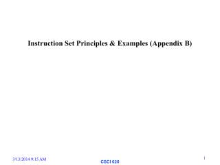
CPU MEM I/O Hierarchical View of EP and Digital Systems Operating System HLLs Computer Architecture State Machines Interface Method Design Techniques MSI Functions Boolean Algebra Gates
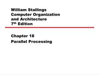
Dbus RW Register File DA AA Const MB MuxB Aout Dout FS Function Unit Status Din MD MuxD Simple Model Data Path (7-18) n-bit bus Signal BA Dbus
Instruction Word 3 3 3 1 5 1 1 DA AA BA MB FS MD RW
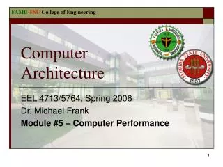
Forecasting the Whole Example Arch from Mano/Kime required 17 control path bits to control that segment of the data path—and surely there are more. For example, we’ve already identified other core regs: Program Counter Memory Add Register Index Register Mem Buffer Register Stack Pointer Status Register Instruction Register
Widening the Control Word An M-bit control word will ultimately be required to control all the architectural elements: M-1 16 0 Mano/Kime: 1st part of the data path Additional data path elements
N N The Overall Organization: Control Path Data Path N M
Implications • Size of instruction word (“opcode”) fetched from memory will be sequence of k, N-bit words If possible, would like k=1; i.e., only a single word fetch per instruction • Control path elements must expand the opcode to produce the required M-bit control path signals
Challenge of single-word opcodes • What needs to be communicated via an opcode? • Operand sources and destinations • Registers • Memory • Constants • Operations • Arithmetic • Logical • Control • Program flow control (Withergoest thou?)
Operand Sources/Destinations • Addressing Modes • Immediate A 27 • Register A R15 • Direct A M(address) • Indirect A M(R15) • Indexed A M(IX+offset)
Opcode Implications… • 1-word opcodes • Register • Indirect • Indexed • 2-word opcodes • Immediate • Direct
Load registers Immediate Memory Indexed Register-to-Register Exchange Registers Stack Operations 8- and 16-bit Arithmetic and Logical Operations Bit Set, Reset, Test Increment/Decrement Shifts and Rotate Block Moves Program Flow Control Control Privileged Instructions Miscellaneous (e.g. NOP) A CISC Instruction Set (Z-World Rabbit)
Example Instructions Load Immediate Data LD A,3 LD HL,456 LD BC',3567 LD H',4Ah LD IX,1234 LD C,54
Instructions to Load or Store Data from or to a Constant Address LD A,(mn) ; loads 8 bits from address mn LD A',(mn) ; not possible on Z180 LD (mn),A LD HL,(mn) ; load 16 bits from the address specified by mn LD HL',(mn) ; to alternate register, not possible Z180 LD (mn),HL
Examples of loading registers using Index Registers LD A,(BC) LD A',(BC) LD (BC),A LD A,(DE) LD A',(DE) LD (DE),A Other 8-bit loads and stores are the following. LD r,(HL) ; r is any of 7 registers A, B, C, D, E, H, L LD r',(HL) ; same but alternate register destination LD (HL),r ; r is any of the 7 registers above LD r,(IX+d) ; r is any of 7 registers, d is -128 to +127 offset LD r',(IX+d) ; same but alternate destination LD (IX+d),r ; r is any of 7 registers or an immediate data byte LD (IY+d),r ; IX or IY can have offset d
Register to Register Move Instructions Any of the 8-bit registers, A, B, C, D, E, H, and L, can be moved to any other 8-bit register, for example: LD A,c LD d,b LD e,l LD dd',BC ; where dd' is any of HL', DE', BC' (2 bytes, 4 clocks) LD dd',DE LD IX,HL LD IY,HL LD HL,IY LD HL,IX LD SP,HL ; 1-byte, 2 clocks LD SP,IX LD SP,IY
Exchange instructions are very powerful because two (or more) moves are accomplished with one instruction. Examples of register exchange instructions include: EX af,af' ; exchange af with af' EXX ; exchange HL, DE, BC with HL', DE', BC' EX DE,HL ; exchange DE and HL
Push and Pop Instructions There are instructions to push and pop the 16-bit registers AF, HL, DC, BC, IX, and IY. The registers AF', HL', DE', and BC' can be popped. Popping the alternate registers is exclusive to the Rabbit, and is not allowed on the Z80 / Z180. Examples POP HL PUSH BC PUSH IX PUSH af POP DE POP DE' POP HL'
Arithmetic and Logical Operations ADD HL,ww ; where ww is HL, DE, BC, SP ADC HL,ww ; ADD and ADD carry SBC HL,ww ; sub and sub carry INC ww ; increment the register (without affecting flags)
Shifts RR HL ; rotate HL right with carry, 1 byte, 2 clocks ; note use ADC HL,HL for left rotate, or add HL,HL if ; no carry in is needed. RR DE ; 1 byte, 2 clocks RL DE ; rotate DE left with carry, 1-byte, 2 clocks RR IX ; rotate IX right with carry, 2 bytes, 4 clocks RR IY ; rotate IY right with carry ;Logical Operations AND HL,DE ; 1 byte, 2 clocks AND IX,DE ; 2 bytes, 4 clocks AND IY,DE OR HL,DE ; 1 byte, 2 clocks OR IX,DE ; 2 bytes, 4 clocks OR IY,DE
Input/Output Instructions The Rabbit uses an entirely different scheme for accessing input/output devices. Any memory access instruction may be prefixed by one of two prefixes, one for internal I/O space and one for external I/O space. When so prefixed, the memory instruction is turned into an I/O instruction that accesses that I/O space at the I/O address specified by the 16-bit memory address used. For example IOI LD A,(85h) ; loads A register with contents ; of internal I/O register at location 85h. LD IY,4000h IOE LD HL,(IY+5) ; get word from external I/O location 4005h
8-bit Bit Set, Reset and Test Instructions Instruction clk A I S Z V C Operation BIT b,(HL) 7 f s - * - - (HL) & bit BIT b,(IX+d)) 10 f s - * - - (IX+d) & bit BIT b,(IY+d)) 10 f s - * - - (IY+d) & bit BIT b,r 4 f - * - - r & bit RES b,(HL) 10 d - - - - (HL) = (HL) & ~bit RES b,(IX+d) 13 d - - - - (IX+d) = (IX+d) & ~bit RES b,(IY+d) 13 d - - - - (IY+d) = (IY+d) & ~bit RES b,r 4 r - - - - r = r & ~bit SET b,(HL) 10 b - - - - (HL) = (HL) | bit SET b,(IX+d) 13 b - - - - (IX+d) = (IX+d) | bit SET b,(IY+d) 13 b - - - - (IY+d) = (IY+d) | bit SET b,r 4 r - - - - r = r | bit
8-bit Increment and Decrement Instruction clk A I S Z V C Operation DEC (HL) 8 f b * * V - (HL) = (HL) - 1 DEC (IX+d) 12 f b * * V - (IX+d) = (IX+d) -1 DEC (IY+d) 12 f b * * V - (IY+d) = (IY+d) -1 DEC r 2 fr * * V - r = r - 1 INC (HL) 8 f b * * V - (HL) = (HL) + 1 INC (IX+d) 12 f b * * V - (IX+d) = (IX+d) + 1 INC (IY+d) 12 f b * * V - (IY+d) = (IY+d) + 1 INC r 2 fr * * V - r = r + 1
Control Instructions - Jumps and Calls Instruction clk A I S Z V C Operation CALL mn 12 - - - - (SP-1) = PCH; (SP-2) = PCL; PC = mn; SP = SP-2 DJNZ j 5 r - - - - B = B-1; if {B != 0} PC = PC + j JP (HL) 4 - - - - PC = HL JP (IX) 6 - - - - PC = IX JP (IY) 6 - - - - PC = IY LCALL xpc,mn 19 - - - - (SP-1) = XPC; (SP-2) = PCH; (SP-3) = PCL; XPC=xpc; PC = mn; SP = (SP-3) LJP xpc,mn 10 - - - - XPC=xpc; PC = mn LRET 13 - - - - PCL = (SP); PCH = (SP+1); XPC = (SP+2); SP = SP+3 RET 8 - - - - PCL = (SP); PCH = (SP+1); SP = SP+2 RETI 12 - - - - IP = (SP); PCL = (SP+1); PCH = (SP+2); SP = SP+3 RST v 10 - - - - (SP-1) = PCH; (SP-2) = PCL; SP = SP - 2; PC = {R,v) v=10,18,20,28,38 only
Miscellaneous Instructions Instruction clk A I S Z V C Operation CCF 2 f - - - * CF = ~CF IPSET 0 4 - - - - IP = {IP[5:0], 00} IPSET 1 4 - - - - IP = {IP[5:0], 01} IPSET 2 4 - - - - IP = {IP[5:0], 10} IPSET 3 4 - - - - IP = {IP[5:0], 11} IPRES 4 - - - - IP = {IP[1:0], IP[7:2]} LD A,EIR 4 fr * * - - A = EIR LD A,IIR 4 fr * * - - A = IIR LD A,XPC 4 r - - - - A = MMU LD EIR,A 4 - - - - EIR = A LD IIR,A 4 - - - - IIR = A LD XPC,A 4 - - - - XPC = A NOP 2 - - - - No Operation POP IP 7 - - - - IP = (SP); SP = SP+1 PUSH IP 9 - - - - (SP-1) = IP; SP = SP-1
Privileged instructions. Privilege means that an interrupt cannot take place between the privileged instruction and the following instruction LD SP,HL IOI LD (STACKSEG),A ;will run w/o fear of Int