Download
1 / 15
150 likes | 276 Views
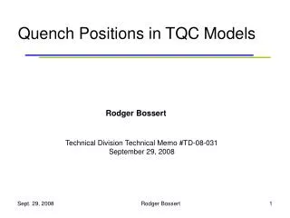
Quench Positions in TQC Models. Rodger Bossert. Technical Division Technical Memo #TD-08-031 September 29, 2008. Technology Quadrupole - TQC. Features: Traditional collared coil with stainless steel shell. Preload shared by collars and shell.

E N D
Quench Positions in TQC Models Rodger Bossert Technical Division Technical Memo #TD-08-031 September 29, 2008 Rodger Bossert
Technology Quadrupole - TQC • Features: • Traditional collared coil with stainless steel shell. • Preload shared by collars and shell. • Preload applied primarily at room temperature. Rodger Bossert
Preload Application - TQC Rodger Bossert
Magnet Tests - TQC Virgin coils in bold. Coils with non-glued poles and pole slots in red. Rodger Bossert
TQC01 Quench History • Low plateau (72% of SSL) at 4.5K with all quenches in inner layer pole turn. • Better performance • (87% SSL) at 1.9K. • Eventual degradation in outer layer lead area in 2 coils. • Almost all quenches in area where outer poles are not glued. • Very few quenches in end areas. 13 10 9 12 Rodger Bossert
TQC01b Quench History • Higher preload gave quench performance similar to that from the coils in TQS01 series. • Same coils have same performance in the different structures. • 1.9K behavior similar to other MJR coils (as expected). • Magnet was disassembled, and coils reused without degradation. Rodger Bossert
Ramp Rate Studies Temp Dep studies 4.5K 20 A/s 1.9K 20 A/s 4.5K 20 A/s 4.5K 20 A/s TQC01b Quench History by Coil Training quenches in all four coils, but more in coils 7 and 8 Quench positions of training quenches Rodger Bossert
10 11 2 3 5 9 6 TQC02E Quench History 4.5 K: Quenches: #2,3,5,6,10,11 - in coil 20 Quench # 6 in outer layer mid-plane Quench # 9 – coil 21 1.9 K: All quenches in outer layer mid-plane segment of coil 21 Quenches at high ramp rates: All in coils 22 and 23, mid-plane segments, both inner and outer coil layer • Similar training behavior as TQS02a with same coils. • 1.9K behavior similar to other RRP coils, seemingly limited by instabilities. • Training at 4.5K not complete due to quenches in leads. • Magnet was disassembled, and coils reused several times without degradation. Rodger Bossert
TQC02a Quench History TQC02a Quench History Key to zones: (1) 4.5K 20A/s, (2) 4.5K ramp rate studies, (3) 1.9K 20 A/s, (4) 1.9K ramp rate studies, (5) Temp Dependence studies, (6) 4.5K ramp rate studies, (7) 4.5K 20 A/s Slow linear training in coil 24 until quench position changed to coil 27, at a specific position near the return end and current of 9250A, 68% of the SSL. 1.9K training was similar to other RRP models, erratic and not better than at 4.5K. However, most quenches even at 1.9K were in the inner coil pole turn. Rodger Bossert
TQC02a Quench Positions TQc02a: Coil 27 • Training quenches all in coils 24 and 27, in the inner coil pole turn but near the junction between outer pole pieces. • Many, including the limiting quenches in Coil 27, near the return end. TQC02a: Coil 24, 4.5 K TQC02a: Coil 24, 1.9 K Rodger Bossert
184 167 150 133 116 100 84 68 Gradient (T/m) TC2 TC1 TQC02b Quench History TQC02b training at 4.5K proceeded in a slow but linear path, with all training quenches at 4.5K in the same coil (12). At 1.9K, all training quenches also in coil 12, except two in coil 17. • Plateau at 4.5K was reached at 10382A, about 84% of the critical current limit, almost identical to that of TQC01b. • Behavior at 1.9K is erratic, still unexplained. • Return to same plateau when returned to 4.5K. • Some retraining during 2nd thermal cycle. Rodger Bossert
2 (5 quenches) 3 (4 quenches) 5 (2 quenches) 1 (20 quenches) 4 (64 quenches) TQC02b Quench Positions at 4.5K Coil 12 1: A10A9 and A9A8 segments starting almost at the same time, A8A6 follows in 5-6 msec. 2: Quenches in both A10A9 and A8A6 segments. 3:A8A6 is the first quenching segment, A9A8 - very close to it. 4: A10A9 is the first quenching segment, then A9A8, A8A6. 5: Quench in ramp. Rodger Bossert
91 92 A6/B3 Coil 12 2 (1 quench) 1 (34 quenches) Coil 17 TQC02b Quench Positions at 1.9K 1: A10A9 and A9A8 segments starting almost at the same time, A8A6 follows in 5-6 msec 2: Quench in ramp 2 training quenches at 1.9K only; The first quenching segment is A8A7 High ramp rate quenches at 1.9K only in mid-plane segments Few quenches during the heater tests The highest quench current in the test: ~ 10.5 kA, quench #92, T=3.6K Did not return to 1.9K after 2nd thermal cycle. Rodger Bossert
TQC Preload and Quench Behavior Preload at inner pole in TQC models (MPa) TQC01b data is listed separately for coils with glued/non-glued outer poles. * Actual values unknown but gauges did not unload during excitation % of SSL in TQC models Rodger Bossert
All TQC 4.5K Training Quenches Training at 4.5K of all TQC models is compared. Coils with potted parts show a steeper rise and earlier plateau, although all are used in an identical structure. Rodger Bossert