Download
1 / 8
80 likes | 418 Views
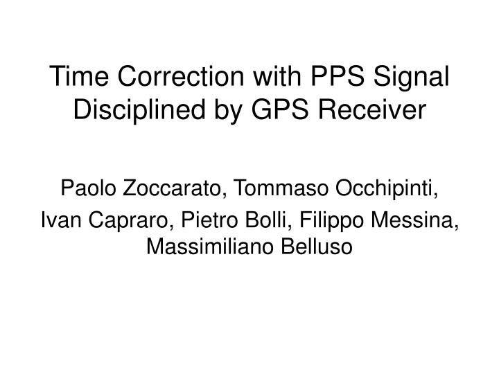
Time Correction with PPS Signal Disciplined by GPS Receiver. Paolo Zoccarato, Tommaso Occhipinti, Ivan Capraro, Pietro Bolli, Filippo Messina, Massimiliano Belluso. PPS data analysis. Counts of the pps signal. Mini -T Trimple specification :. PPS acquired during Feige observation.

E N D
Time Correction with PPS Signal Disciplined by GPS Receiver Paolo Zoccarato, Tommaso Occhipinti, Ivan Capraro, Pietro Bolli, Filippo Messina, Massimiliano Belluso
PPS data analysis Counts of the pps signal Mini-T Trimple specification: PPS acquired during Feige observation Counts differences of the pps signal About 600 counts, i.e. ~15 ns About 2150 counts, i.e. ~ 54 ns
Estimation of the initial reference period Fit curve equation: Removing the linear and quadratic terms we obtain: 670 counts On average there is a 1 pps every 40959748112.9816 counts, then the real length of the TDC initial reference period is:
PPS time The estimation error is about 137 counts, i.e. ~3.4 ns Determined the real initial reference period we convert the counts in time: Now we must remove the residual error respect to the ideal time due to the oscillator drift and offset
Oscillator parameters estimation The fit curve equation is: The fit error is about 360 ns: Removing the oscillator offset and drift we obtain the stochastic residual of the oscillator: The estimated initial error phase, offset and drift coefficients can be used to correct the time tags of Feige.
Oscillators stochastic noise The stochastic residuals are on the order of 10-6 [sec], according with the values of a quartz oscillator. The residual noise is a flicker phase noise (see figure above), the predominant noise on the Quartz oscillators in the short period, as it is possible to see in the table at the right. W = white, F = flicker, RW = random walk, FM = frequency modulation, PM = phase modulation
Crab analysis • We have realized two Matlab functions to correct the time tags. • To correct the Crab data we don’t have the pps data, so we used pps data acquired during Feige Observation • The period of the Crab without this correction is 30.61 ms, while with the correction is 33.61 ms. • Crab period became very close to its real period (33.71 ms).