
Title…………………………………………………………………….
Title……………………………………………………………………. Author 1 Name and Surname, Author 2 Name and Surname and Author 3 Name and Surname. Author 1 affiliation , Department of Electrical Engineering , Faculty of Technology, University of Tébessa, Algeria

Title…………………………………………………………………….
E N D
Presentation Transcript
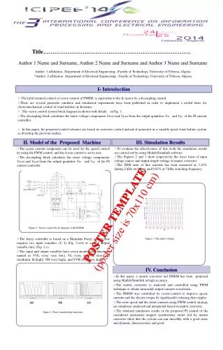
Title…………………………………………………………………….Title……………………………………………………………………. Author 1 Name and Surname, Author 2Name and Surname and Author 3 Name and Surname Author 1 affiliation , Department of Electrical Engineering , Faculty of Technology, University of Tébessa, Algeria *Author 2 affiliation , Department of Electrical Engineering , Faculty of Technology, University of Tébessa, Algeria I- Introduction • The field oriented control or vector control of PMSM is equivalent to the dc motor by a decoupling control • There are several generator emulator and simulation experiments have been published in order to implement a useful basis for electromechanical control of wind turbines in literature. • The vector control system block diagram in shown with details in Fig. 1. • The decoupling block calculates the stator voltage components Vdsref and Vqsref from the output quantities Vds and Vqs of the PI current controller. • In this paper, the proposed control schemes are based on converter control instead of generator in a variable speed wind turbine system as diverting the previous studies. II. Model of the Proposed Machine III. Simulation Results • The q-axis current component can be used for the speed control by using the PWM control, and the d-axis current is set to zero. • The decoupling block calculates the stator voltage components Vdsref and Vqsref from the output quantities Vds and Vqs of the PI current controller. • To evaluate the effectiveness of this work the simulation results are carried out by using Matlab/Simulink software. • The Figures 2 and 3 show respectively the wave form of input voltage source and output simple voltage of matrix converter • The THD ratio of line currents has been measured as 3.25% during 2 kHz switching and 0.03% at 5 kHz switching frequency. POSTER TEMPLATE (poster size is 70x110 cm) • Figure 1. Vector control block diagram of the PMSM • The fuzzy controller is based on a Mamdani Fuzzy system that requires two input variables (V, f) (Fig. 2.a-b) to control output variable (mi), (Fig. 2.c) . • The input and output variables have seven membership functions named as VVL (very very low), VL (very low), L (low), M (medium), H (high), VH (very high), and VVH (very very high). • Figure 3. The input voltages IV. Conclusion • In this paper, a matrix converter fed PMSM has been proposed using Matlab/Simulink in high accuracy. • The matrix converter is analyzed and controlled using PWM technique to obtain sinusoidal output currents waveforms. • The PMSM was controlled by vector-control to improve speed, currents and the electric torque by significantly reducing their ripples. • The rotor speed and the stator currents using PWM control strategy are simulated, analyzed and interpreted based on matrix converter. • The obtained simulation results of the proposed PI control of the considered permanent magnet synchronous motor fed by matrix converter show that the system can run smoothly with a good static and dynamic characteristics and good • Figure 2. Fuzzy membership functions