Download
1 / 65
660 likes | 900 Views
An introduction to VMEbus. Markus Joos, CERN. Overview What you already should know VMEbus Introduction Addressing Single cycles Block transfers Interrupts VME64x System assembly Single Board Computers Software Tools. O. 011111011110. What you already should know.

E N D
An introduction to VMEbus Markus Joos, CERN Overview • What you already should know • VMEbus • Introduction • Addressing • Single cycles • Block transfers • Interrupts • VME64x • System assembly • Single Board Computers • Software • Tools O 011111011110 M. Joos – Introduction to VMEbus
What you already should know • C(++) programming • use of pointers • signals • data types (char, short, int) • (use of C++ methods) • Linux • Makefiles • gdb • Shared libraries • Usually the environment variable LD_LIBRARY_PATH tells the linker where to find shared libraries • Handling drivers (insmod, device nodes, files in /proc) • General operation (cd, ls, mkdir, etc.) M. Joos – Introduction to VMEbus
Falklands War First implantation of an artificial heart Michael Jackson - Thriller IEEE 1014 - VMEbus Foundation of Sun Microsystems First computer virus 1982 M. Joos – Introduction to VMEbus
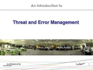
VMEbus in action The VMEbus crates of the ATLAS RPC detector M. Joos – Introduction to VMEbus
VMEbus in action A single ROD crate Processor board TTC interface Detector interface M. Joos – Introduction to VMEbus
VMEbus in action More examples of VMEbus systems in ATLAS In total there are about ~150 crates in ATLAS and they will stay for another 5-10 years M. Joos – Introduction to VMEbus
Why VMEbus? • (Complex) DAQ systems usually require custom built electronics modules which have to be: • Housed • Powered • Configured • Read out • VMEbus has traditionally been the technology of choice in many HEPexperiments and accelerator control systems because it offers features such as: • A well proven open standard that includes mechanical, electrical and protocol sections • Suitable card sizes • A data transfer protocol that is relatively easy to implement • An “ecosystem” of third party products (crates, processors, I/O modules, etc.) which are supported by the manufacturers for long durations • Currently there are more than 1000 VMEbus systems at CERN (accelerator & experiments) M. Joos – Introduction to VMEbus
VMEbus mechanics VMEbus cards exist in 3 standard heights: 3U, 6U and 9U (1U = 1.75 inch) and 2 depths: 160 mm (3U, 6U) and 340 mm (9U) 9U 3U 6U 160 mm 340 mm 160 mm All cards are 0.8 inch (20.3 mm) wide M. Joos – Introduction to VMEbus
P1 Backplane Backplane J1 3U module Backplane P1 J1 6U transition module J1 P0 J0 J0 P2 J2 6U module J2 9U transition module J3 P1 P0 P2 P3 9U module VMEbus mechanics (2) In 6U and 9U systems there can be transition modules installed on the rear side of the backplane. Transition modules do not connect to VMEbus but just to the VMEbus module on the opposite side of the backplane via the user defined pins of the J0, J2 and J3 connectors M. Joos – Introduction to VMEbus
40 kg VMEbus mechanics (3) Example: 6U VME64x module Alignment pin Incompatible with certain old crates 5 row P1 connector 160 pins used for VMEbus Insertion force (415 pins * 1 N) P0 connector Used for PMC I/O Incompatible with certain crates (Jaux, VME64xP) Injector / extractor handles Push button 5 row P2 connector 32 pins used for VMEbus Other pins user defined (e.g. for transition modules) Discharge strip M. Joos – Introduction to VMEbus
VMEbus crates 21 slot 9U crate (with 6U section) for 19” racks 21 slot 6U crate for 19” racks • There are different types of power supplies (5V, +/- 12V, 3.3V, 48V) mounted locally or remotely • The fan-tray unit allows to monitor parameters like voltages, currents, fan speeds, temperatures • (Some) crates can be remotely controlled e.g. by a field bus (CAN) • ATTENTION: The EMC gasket to the left of slot 1 may damage your VMEbus cards M. Joos – Introduction to VMEbus
VMEbus Backplane BG0 J1 BG1 Daisy-chain jumpers (only on some old backplanes) BG2 BG3 J0 IACK J2 J3 (9U crates only) Slot 1 Front view Automatic 6U VME64x backplane M. Joos – Introduction to VMEbus
VMEbus basics • Classes of modules (logical) • Master • A module that can initiate data transfers • Slave • A module that responds to a master • Interrupter • A module that can send an interrupt (usually a slave) • Interrupt handler • A module that can receive (and handle) interrupts (usually a Single Board Computer) • Arbiter • A piece of electronics (usually included in the SBC) that arbitrates bus access and monitors the status of the bus. It should always be installed in slot 1 of the VMEbus crate if interrupts are used M. Joos – Introduction to VMEbus
VMEbus basics (2) • Electrical properties • All lines use TTL levels • Low = 0 ... 0.6 V • High = 2.4 ... 5 V • Address, address modifier and data lines are active high • Protocol lines (e.g. AM, LWORD, DS0/1) are active low • Protocol • Asynchronous with 4-edge handshaking • The duration of a VMEbus cycle depends on the speed of the master and the slave • Byte ordering • VMEbus is big endian. It stores the most significant byte of a 32-bit word at the lowest byte address (0x0) • PCI and Intel CPUs are little endian. They store the most significant byte of a 32-bit word at the highest byte address (0x3) • Most (but not all) VMEbus masters (e.g. VP110) have automatic byte swapping logic M. Joos – Introduction to VMEbus
VMEbus basics (3) • Main types of data transfers • Single cycles • Transfer 8, 16 or 32 bits of data (typically) under the control of the CPU on the master • Mnemonic: D8, D16 and D32 • Typical duration: 1 µs + S/W overhead • Block transfers (DMA = Direct Memory Access) • Transfer any amount of data (usually 32 or 64 bit at a time) under the control of a DMA controller (CPU independent) • Mnemonic: D32BLT and D64MBLT • Data is transferred in bursts of up to 256 (D32) or 2048 (D64) bytes • Typical duration: 150 ns per data word • Interrupts • Used typically by slaves to signal a condition (e.g. data available, internal error, etc.) • Can (in principle) have 7priorities • The interrupter provides an 8-bit vector on request of the interrupt handler to identify itself • ROAK (Release on Acknowledge) or RORA (Release On Register Access) • VMEbus addresses • Either 16, 24 or 32 valid bits. Mnemonic: A16, A24 or A32 • A40 and A64 defined but very rarely used M. Joos – Introduction to VMEbus
VMEbus protocol Why do I have to understand how the protocol works if I am not designing cards? • Some designers make mistakes and their VMEbus cards do not work at all or fail in combination with certain other cards • Debugging VMEbus traffic by S/W (printf(), gdb, etc.) is difficult or even impossible • A great help for fixing such problems are VMEbus analyzers • A VMEbus analyzer also tells you if you are really executing the desired types of cycles (e.g. D8, D16, D32, etc.) • In order to understand the output of such an analyzer you have to have some knowledge of the protocol M. Joos – Introduction to VMEbus
Important signals Note: “*” denotes active low signals M. Joos – Introduction to VMEbus
Arbitration • Before a master can transfer data it has to request the bus. It does this by asserting one of the four bus request lines • These lines (BR0, BR1, BR2 and BR3) can be used to prioritize requests in multi-master systems • The arbiter (usually in slot 1) knows (by looking at the BBSY line) if the bus is busy or idle. Once it is idle it asserts one of the four Bus Grant out lines (BGOUT 0..3) • If a master detects a “1” on the BGIN line corresponding to its BR it claims the bus by asserting BBSY (otherwise it passes BGIN on to BGOUT to close the daisy chain) Slot N Slot N+1 BR* BG* BBSY* BGIN BGOUT BG daisy chain Color code: Arbiter - Master M. Joos – Introduction to VMEbus
Arbitration (2) • The arbiter can use different schemes: PRI (priority based), RRS (round robin) • Not an issue for single master systems • If two masters use the same bus request level the one closer to slot 1 inherently has a higher priority (because it detects BGIN first) • Modern masters support “fair arbitration”. I.e. they delay their bus request if other masters are requesting the bus at the same level • A master may get stuck if the BG daisy chain is not closed M. Joos – Introduction to VMEbus
Addressing • The VMEbus backplane has 31 address lines: A01..A31 • There is no A00 address line on the backplane. This information is encoded in the DS0/1 protocol lines • A slave is selected by two criteria: • Address (usually 16, 24 or 32 valid bits) • Address modifier (6 bits). It defines: • The number of valid address bits • The access mode (user/supervisor, program/data, CR/CSR) • The transfer type (single cycle or block transfer) • Typically slaves respond to only one address width (A16, A24 or A32; read the manual of the slave) but may allow both single cycles and block transfers • The base address of a slave can be set: • Mechanically: on-board Jumpers, DIP switches • By S/W: VME64x geographical addressing, CR/CSR M. Joos – Introduction to VMEbus
invalid invalid invalid valid valid valid Addressing protocol • First the masterdrives AM, Address and LWORD*. Then it waits 35 ns and finally drives AS* to validate the information • The slave has to decode the address information within 40 ns (even though most masters keep AS* asserted much longer) • The master does not know if a slave has accepted the address information. It continues with the data transfer until it either receives a DTACK* or a BERR* • If two or more slaves believe to be addressed you have a problem… AM[5..0] The timing parameters mentioned here are two of about 50 in the VMEbus standard. The standard also distinguishes master and slave timing (bus skew) LWORD* A[31..1] AS* 35 ns 40 ns Color code: Master M. Joos – Introduction to VMEbus
Single cycles Example: (Simplified) write cycle BR* BG* AS* Address/AM Data DS* DTACK* BERR* Arbitration 1:Master drives address and AM code. Then it asserts AS 2:Master puts data on the bus. Then it asserts DS 3:Slave latches data and drives DTACK 4:Master removes DS 5:Slave removes DTACK 6:Master releases Address, AM and data lines. Then it releases AS 6 1 undefined defined undefined undefined defined undefined 2 5 3 4 Color code: Master - Slave - Arbiter M. Joos – Introduction to VMEbus
Single cycles (2) • The number of bytes to be transferred (1, 2 or 4) is encoded in the DS0, DS1 and LWORD protocol lines • Remember that some slaves support only certain data widths (e.g. D8 and D16 but not D32) • The VMEbus address should be alignedto the data size • Reading a D32 word e.g. from address 0x000003 may not be a good idea • VMEbus also supports (rarely used) read-modify-write cycles (useful for semaphores) • Remember that VMEbus is big endian. Example: M. Joos – Introduction to VMEbus
Example: D32 write Block transfers AS Address/AM Data DS DTACK undefined undefined defined • The Block transfer protocol is based on the single cycle protocol • The address lines on the backplane do not change state during the transfer. Both master and slave use internal counters to keep track of the address • As the address lines are not used they can carry data: 64-bit multiplexed DMA In this case the slave uses DTACK for two purposes: • Directly after the assertion of AS to acknowledge the address • After each assertion of DS to acknowledge the data undefined defined undefined defined defined defined Color code: Single cycle protocol – block transfer M. Joos – Introduction to VMEbus
Block transfers (2) • A master must not cross a 256 bytes (D32) or 2048 bytes (D64) address boundary respectively without releasing AS (transparent to the user) • This is to give other masters a chance to acquire the bus before too long • Reading out single address FIFOs is not foreseen by the standard and requires special masters • Designing a slave that terminates a block transfer from a FIFO with a bus error is legal but bad practice. It does not always work with the Tundra Universe chip • VMEbus interface chips may require a relative alignment of the remote (VMEbus) and local (PCI) addresses • In case of the Tundra Universe the VMEbus and PCI addresses must be 8-byte aligned with respect to each other • Contiguous buffers • Memory obtained with malloc()may be fragmented. Most DMA controllers, however, need contiguous buffers • Contiguous buffers can be provided by special drivers (e.g. ATLAS: cmem_rcc) based on kernel functions (e.g. get_free_pages) or extensions of the Linux kernel (BigPhysArea) M. Joos – Introduction to VMEbus
VMEbus typical performance • Being a handshaked, asynchronous protocol there is no fixed transfer rate. The timing parameters (see VMEbus standard) however set an upper limit. • Single cycles: Typical performance = 1 µs per transfer • D8 = 1 MB/s • D16 = 2 MB/s • D32 = 4 MB/s • Write posting decouples PCI and VMEbus cycle. This increases the performance to ~ 10 MB/s for D32 • Block transfers • D32 = 20..25 MB/s (theoretical: 40 MB/s) • D64 = 40..50 MB/s (theoretical: 80 MB/s) M. Joos – Introduction to VMEbus
Bus errors • In VMEbus errors can occur under two conditions • A slave has been addressed but is incapable of performing the requested transfer. In this case the BERR signal is issued by the slave and reaches the master within a few µs. • The master has issued an address that no slave recognizes. Such cycles get terminated by the bus monitor (arbiter) by asserting BERR after a programmable delay (typical values are 16 or 256 µs) • There is no standard way for the delivery of a BERR from the VMEbus interface to the CPU of the master • On PowerPCs BERR is typically converted directly to a non-maskable interrupt and then converted to the SIGBUS signal by the operating system • Certain (old) Intel based SBCs ignore bus errors • Other Intel based SBCs convert it to a regular PCI interrupt. This interrupt is typically handled by the VMEbus driver and converted to the SIGBUS signal M. Joos – Introduction to VMEbus
Interrupts • VMEbus provides 7 interrupt levels (= bus lines) to prioritize interrupts • Each interrupter can use any level • There must only be one interrupt handler for each level • The interrupt handler uses (under H/W control) a special type of single cycle (IACK cycle) to obtain an 8-bit vector from the interrupter. This vector (set by jumpers or S/W) must be unique (within the crate) and identifies the source of the interrupt • There are two types of interrupters: • ROAK (preferred) • The IACK cycle clears the interrupt • RORA • The interrupt is cleared by an additional register access (single read or write cycle) • Typically an interrupt gets handled by the H/W in a few µs (once the VMEbus is free). However there can be additional (possibly large) S/W overheads depending on the operating system used and the state of the CPU • If two interrupters are active at the same time and on the same level the one closer to slot 1 will be serviced first (IACK daisy chain) Slot N Slot N+1 IACKIN IACKOUT M. Joos – Introduction to VMEbus
VME64x • VME64x is a set of extensions to the VMEbus standard made in 1997 • Most features are optional and fall into one of four categories: • Mechanics • 5-row P1/J1 and P2/J2 connectors • J0/P0 connector • Alignment pin • EMC gaskets • Injector / extractor handles • Discharge strips • Card keys • Solder side covers • Plug-and-play • Geographical addressing (access a module by its slot number) • CR/CSR space: Standardised registers for the automatic configuration of a module (base address(es), interrupt vector(s), etc.) • Power • 3.3 V and 48 V • Additional 5 V • 2eVME Protocol: A rarely used way of speeding up block transfers (theoretical bandwidth: 160 MB/s) M. Joos – Introduction to VMEbus
CR/CSR space access and geographical addressing • “Classic” VMEbus slaves use on-board jumpers or switches for the initialization of the base address and the interrupt vectors • The VME64(x) standard proposes a S/W based mechanism (plug-and-play) The basic principles are: • Each slave has a special window of 512 kB consisting of a Configuration ROM (CR) and a Control and Status Register (CSR) section • Access to this window is in A24 mode with AM=0x2f • The address of that window is either set by jumpers (VME64) or derived from the slot number (geographical addressing, VME64x) with the formula: address = slot# * 0x80000 • The CR/CSR space contains many (mostly optional) features to specify and control the functions of a slave board • Slave boards are identified by a manufacturer + board ID stored in the CR. These IDs have to be unique • The most important CSR space registers are the eight ADER registers. They are used to define the base address(es) of the main function(s) of the slave. M. Joos – Introduction to VMEbus
2eSST • 2eSST = 2 edge Source Synchronous Transfer • An addition to the VME64x standard (since 1999) • It defines a synchronous protocol for VMEbus block transfers • Three transfer speeds are defined: 160, 267 and 320 MB/s (8 bytes @ 20, 33.3 and 40 MHz) • Allows for data broadcast and multicast • Works only reliably on high quality backplanes (incident wave switching) and with special (Texas Instruments) driver chips • There exist (so far) only a hand full of VMEbus modules built to this standard M. Joos – Introduction to VMEbus
The VMEbus single board computer • Usually this is the only master and interrupt handler in the crate • It often also provides the arbiter functionality (and should therefore be installed in slot 1, despite what will be said about cooling) • It behaves like a normal PC • Operating system: Linux, (RT OS, Windows) • Development tools: gcc, g++, gdb • Environment: Shell, Xterm, vi, emacs • Accessed via: RS232, Ethernet, VGA • It interfaces to VMEbus via a PCI device • Typically Tundra Universe / IDT Tsi148 • Depending on the model and the S/W used the VMEbus I/F has to be configured in the BIOS or at start-up by special programs • Some SBCs can be equipped with mezzanines (PMC, IP) but this is another story M. Joos – Introduction to VMEbus
The VP110 SBC (used in the exercises) M. Joos – Introduction to VMEbus
Other VMEbus masters and interfaces • PC to VMEbus interfaces • Available from several manufacturers • A set typically consists of a PCI card, a VMEbus card and a cable (copper or optical fiber) • Also available: VMEbus master with USB interface • VMEbus repeaters • Allows a master in crate 1 to access a slave in crate 2 • A set consists of two VMEbus cards and a cable • There is usually a performance penalty • VMEbus to CAMAC interface • Allows a master in a VMEbus crate to control a CAMAC crate • A set consists of a VMEbus slave, a CAMAC crate controller and a cable M. Joos – Introduction to VMEbus
Subsystem buses The P0, P2 and P3 connectors have a number of user defined pins. They can be used to implement specialized communication channels independently from the VMEbus protocol. Examples: • VXS (-> next lecture) • A recent addition to the standard • It allows each VMEbus card to connect to a switch fabric. • Initially it uses the Ethernet protocol but other technologies (e.g. PCIe) are possible as well • Custom P3 • In 9U crates the P3 is totally user defined • Special backplanes are possible too • VSB (VME Subsystem Bus) • Obsolete. • Provides a 32 bit bus for up to 8 adjacent cards • Was used to interface to FASTBUS M. Joos – Introduction to VMEbus
System integration • Find the right crate for your modules • J0 / Jaux incompatibility • VME64x (alignment pin, geographical addressing) • Find out if your crate still has BG/IACK jumpers • Rule: Each slot must be equipped with 1 card or 5 jumpers • Attention: Jumpers may be on either side of the J1 connector depending on backplane type • Card handling and insertion • VMEbus cards can be sensitive to electrostatic discharge. Take precautions • Never add or remove a card if the crate is switched on • Depending on the type of module the insertionforce is between 20 and 50 kg. Check twice that the card really has been inserted properly!! • Do not trust LEDs on the front panel. On certain (VME64x) cards the power pins are longer than the protocol pins. • Cooling • Avoid installing CPUs in the leftmost or rightmost slot (there are special arbiter modules) • Leave one or two slots empty between cards, if possible • Close the front of the crate with blind panels • Check the fan speed • Check if your VMEbus cards have temperature sensors • Address lay-out • Check that the address windows of the slave modules do not overlap • Try to map similar slaves (e.g. A32, A24) to consecutive address ranges M. Joos – Introduction to VMEbus
VMEbus S/W True “Real time” S/W is rarely required (→ buffer chains) (Linux) Drivers • In (almost) all cases access to the VMEbus is via a device driver • The driver allows to use the VMEbus in multi-processing environments • Interrupts are handled by the driver and signalled to the user application e.g. by means of signals or semaphores • The drivers typically provide DMA request lists. A block transfer may therefore not take place immediately but be delayed by other DMA requests • Accessing the bus via a driver has disadvantages too • Additional overhead due to context switching (S/W overhead can be 10 * H/W latency) • Drivers are difficult to debug • Sometimes commercial drivers lack desirable features and performance • The “ATLAS approach”: We have developed our own driver and library • Reduces dependency on commercial companies • Allows for the implementation of performance optimized code • Driver can be bypassed for fast H/W access • Use of contiguous memory optimizes transfer of large blocks of data • May not be justifiable for smaller projects M. Joos – Introduction to VMEbus
VMEbus S/W (2) Libraries • The driver is not used directly by the application but via a user library • There is no standard API for such libraries • Switching from one type of master to another imposes issues for S/W portability Performance optimization • Avoid memcopy(); just pass pointers • Avoid context switching (bypass drivers) • Avoid single cycles (this may require special features at the H/W level) • Use contiguous buffers (for efficient DMA) • Don’t be too generous with interrupts (less context switching) • Only implement the features you need (e.g. multi-processing support) • Understand the latencies in your S/W -> profiling M. Joos – Introduction to VMEbus
Debugging tools • H/W (Examples) • VMEtro VBT325 bus analyzer • Stores up to 16000 VMEbus cycles • Powerful trigger and sequencer • Supports protocol analysis • To operate it you need a VT100 (Falco) terminal or a PC with a terminal program (e.g. HypeTerm, minicom, kermit, putty) • CES VMDIS8004 • Low cost bus monitor. Displays the most recent cycle • Can latch the first cycle with a bus error or an interrupt • Has a built in arbiter (useful if SBC runs hot in slot 1) • S/W • Standard tools for code debugging (gdb, printf(), etc.) • Special tools depend on the S/W package Note: This slide contains product placement M. Joos – Introduction to VMEbus
Links for further information • VMEbus standard • www.vita.com (unfortunately the standard is open but not freely available) • Atlas S/W • https://edms.cern.ch/document/325729/4 • https://edms.cern.ch/document/349680/2 • https://edms.cern.ch/document/336290/3 • https://edms.cern.ch/file/325729/4/wrapper.pdf • Alternative open source VMEbus drivers for the Universe chip • http://www.vmelinux.org/(Webpage last changed on May 24, 2003) • VMEbus market overview • http://www.vita.com M. Joos – Introduction to VMEbus
The End M. Joos – Introduction to VMEbus
Additional slides The slides below provide additional information at a more detailed level. Some of them are based on the VMEbus S/W that was developed at CERN for the ATLAS and ALICE experiments. Keep in mind that the library functions and applications of this S/W package are different from other (commercial or public domain) packages for VMEbus access M. Joos – Introduction to VMEbus
Use of pointers to generate VMEbus cycles unsigned int ui_data, *ui_ptr, virtual_address; unsigned short us_dat, *us_ptr; unsigned char uc_data, *uc_ptr; Main() { virtual_address = Map_VME_module(physical_address, AMcode , …); //Hypothetical function ui_ptr = (unsigned int *) virtual_address; us_ptr = (unsigned short *) virtual_address; uc_ptr = (unsigned char *) virtual_address; ui_data = *ui_ptr; //D32 read *ui_ptr = ui_data; //D32 write us_data = *us_ptr; //D16 read *us_ptr = us_data; //D16 write uc_data = *uc_ptr; //D8 read *uc_ptr = uc_data; //D8 write ui_data = ui_ptr[0]; // equivalent to *ui_ptr; ui_data = ui_ptr[4]; // Read D32 at offset 0x10 (4 * 4 bytes) uc_data = uc_ptr[4]; // Read D8 at offset 0x4 (4 * 1 byte) } M. Joos – Introduction to VMEbus
Signal handling #include <signal.h> //Prototypes void SigBusHandler(int signum); main { struct sigaction sa2; sigemptyset(&sa2.sa_mask); sa2.sa_flags = 0; sa2.sa_handler = SigBusHandler; stat = sigaction(SIGBUS, &sa2, NULL); if (stat < 0) { printf("Cannot install SIGBUS handler (error=%d)\n", stat); exit(-1); } } void SigBusHandler(int signum) { printf(“Bus error received\n”); } M. Joos – Introduction to VMEbus
Managing drivers • Is my driver loaded? • /sbin/lsmod • In what state is my driver? • more /proc/<name> (value of name depends on the driver used. ATLAS: “vme_rcc”, “cmem_rcc” or “io_rcc”) • Is the driver currently used • /sbin/lsmod • Check the “Used by” number in the third column. • How to restart a driver • “Used by” has to be 0 • su (then enter root password) • cd /etc/rc.d/init.d • <name> restart (e.g. “vme_rcc restart”) M. Joos – Introduction to VMEbus
(Common) VMEbus AM codes M. Joos – Introduction to VMEbus
Other information • For the ATLAS VMEbus library there is a C++ wrapper • https://edms.cern.ch/file/325729/4/wrapper.pdf M. Joos – Introduction to VMEbus
Glossary ACFAIL: A line on the VMEbus backplane driven by the power supply. If asserted the +5V power will be available for at least an other 4 ms and then drop below 4.875 V BBSY: The protocol line that indicates if the bus is being used (Bus Busy) BERR: The protocol line that signals a bus error BG0..3: Protocol lines used by the arbiter to grant the bus to a master BR0..3: Protocol lines used by masters to request the bus CR/CSR: Configuration ROM / Control and Status Registers, a feature of VME64(x) slave cards for the plug-and-play configuration of the on-board functions Daisy chain: Some of the signal lines of a VMEbus backplane are not bussed but connect only two adjacent slots. In order to pass a signal from slot N to slot N+m the VMEbus modules in between these slots have to pass the signal from the input side to the output side. In case of an empty slot the connection has to be made mechanically (jumper) or automatic (special backplane) DMA: Direct Memory Access (block transfers) EMC: ElectroMagnetic Compatibility: IACK: Protocol line used for the interrupt handshake J0, J1, J2, J3: The female jacks (connectors) on the VMEbus backplane Jaux: A special connector sitting between J1 and J2 on some backplanes used at CERN. Required for certain front-end modules but incompatible with the P0 connector of VME64x P0, P1, P2, P3: The male plugs on VMEbus cards connecting to the backplane ROAK: Release On AKnowledge, A type of VMEbus interrupter that clears the interrupt in response to the IACK cycle RORA: Release On Register Access, A type of VMEbus interrupter that requires a special intervention from the master to clear an interrupt SBC: Single Board Computer SYSFAIL: A VMEbus line that indicates a problem with one card. SYSFAIL can be monitored e.g. by an SBC where it would be converted to an interrupt Write Posting: A way of speeding up single write cycles. The PCI cycle gets acknowledged before the VMEbus cycle completes. This decoupling of the busses increases the speed but can complicate the detection of bus errors M. Joos – Introduction to VMEbus
The Tundra Universe II ASIC • Bridges VMEbus to PCI • Used on most of the commercially available VMEbus processors M. Joos – Introduction to VMEbus
The ATLAS vme_rcc package • The vme_rcc package contains the default VMEbus driver and library • Documentation: https://edms.cern.ch/document/325729/4 • Supported H/W: Concurrent Technologies VP110 as well as other SBC from that company. • The source code of both the driver and the library has been fully developed at CERN and tested on Linux kernels up to 2.6.18 • Why not using an existing VMEbus driver instead of developing a new one? • We wanted to have a sufficiently generic API that could easily be implemented for any VMEbus interface on a SBC • Most drivers for the Universe chip lack support for some features • External code is not necessarily optimized for your type of applications M. Joos – Introduction to VMEbus