Download

1 / 48
480 likes | 605 Views
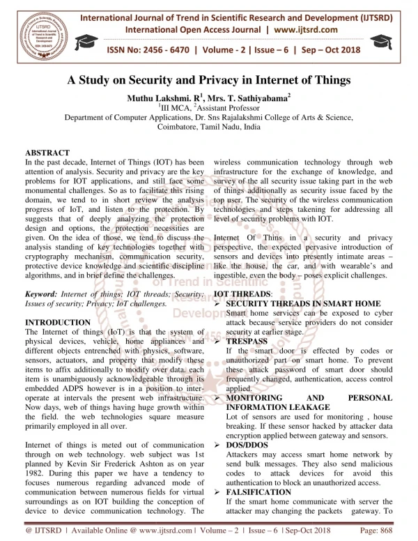
This presentation reviews techniques for detecting and preventing Denial of Service (DoS) attacks, distinguishing between detection and prevention strategies. It discusses network monitoring solutions to identify service violations and types of attacks. The paper categorizes the nature of DoS attacks into various operational forms, affecting network traffic and legitimate connections. Proposed methods include ICMP Traceback messages for tracing attack origins and probabilistic packet marking to efficiently trace paths. Overall, the analysis provides insights into strategies for selecting the most effective defenses against DoS threats.

E N D
Security and Privacy on the Internet Survey Fall 2004 031-60-564 Presentationby Costel Iftimie
I. Ashan Habib, Mohamed Hefeeda, Bharat Bhargava, “Detecting Service Violations and DoS Attacks”, Network and Distributed System Security Symposium (NDSS), Conference Proceedings, 2003II. John Ioannidis and Steven M. Bellovin, “Implementing Pushback: Router-Based Defense Against DDoS Attacks”, NDSS, Conference Proceedings, February 2002. 03-60-564 ci Fall04
I. The first paper presents: a. a short classification and a description of DoS and QoS attacks, b. a solution for network monitoring in order to catch service violations and DoS attacks. c. a comparison between all different situations, with their respective merits and guidelines on selecting the appropriate scheme. 03-60-564 ci Fall04
The paper divides the dealing with DoS attacks into detection and prevention approaches. The detection process has two phases: detecting the attack and identifying the attacker. A DoS attack include attempts to: 1. "flood" a network, preventing legitimate network traffic. 2. disrupt connections between two machines, preventing access to a service. 3. prevent a particular individual from accessing a service. 4. disrupt service to a specific system or person. 03-60-564 ci Fall04
Attacker A1 launches an attack on the victim V. A1 spoofs IP address of host H5 from domain D5. Another attacker A3 uses host H3 as a reflector to attack V. 03-60-564 ci Fall04
Attackers can do considerably better still by structuring their attack traffic to use reflectors. A reflector is any IP host that will return a packet if sent a packet. So, for example, all Web servers, DNS servers, and routers are reflectors, since they will return SYN ACKs or RSTs in response to SYN or other TCP packets; as are query replies in response to query requests, and ICMP Time Exceeded or Host Unreachable messages in response to particular IP packets. Paxson [20] analyzes several Internet protocols and applications and concludes that DNS servers, Gnutella servers, and TCP-based servers are potential reflectors. 03-60-564 ci Fall04
Bellovin [2] proposes an ICMP Traceback message to solve this problem. When forwarding packets, routers can, with a low probability, generate a Traceback message and sends it to the destination. An ICMP Traceback message contains the previous and next hop addresses of the router, timestamp, portion of the traced packet, and authentication information. In Figure 1, while packets are traveling the path from the attacker A1 to the victim V, the intermediate routers (R1; R2; R3; R4; R5; and R6) sample some of these packets and send ICMP Traceback messages to the destination V. With enough messages, the victim can trace the network path A1 to V. The downside of this approach is that the attacker can send many false ICMP Traceback messages to confuse the victim. 03-60-564 ci Fall04
Barros [1] suggested ICMP Traceback messages. His strategy is based on the fact that routers can send ICMP Traceback messages to the source. In the above figure, A3 initiates a DDoS attack by sending TCP SYN segments to the reflector H3 specifying V as the source. H3, in turn, sends SYN ACK segments to the victim V. As a result, routers on the path A3 to H3 will send ICMP messages to the source, V. This reverse trace helps the target to find the attacker. This mechanism does not depend on the number of reflectors, but only on the number of the attackers. 03-60-564 ci Fall04
Snoeren [23] suggested a hashed-based system able to trace the origin of a single IP packet delivered by a network recently. The system is named “source path isolation engine (SPIE)”. This system uses an interesting solution to collect data about packets traveling a determined router. The solution is based on using n bits of hashed value of the packet to set an index of a 2n-bit “digest table”. After the victim detects an attack, a query is sent to SPIE, which queries routers for packet digests of that particular time to determine the source of the attack. 03-60-564 ci Fall04
Burch and Cheswick [5] propose to inscribe path data into the header of the packets. This marking can be deterministic or probabilistic. In the deterministic marking, every router marks all packets. The pitfall is that the packet header grows with every hop increase on the path. The probabilistic packet marking (PPM) encodes the path information into a small fraction of the packets. The assumption is that during a flooding attack, a huge amount of traffic travels towards the victim. Thi way, there is a considerably high chance that a lot of these packets will be marked at routers during their ride. Chances are that the marked packets will have enough data to trace the network path back from the target to the source of the attack. 03-60-564 ci Fall04
+Savage et al. [21] presents efficient methods to encode the path data into packets using “exclusive OR” of two IP addresses and a distance metric. Consider the attacker A1 and the victim V in the above figure. Let’s say that there is one hop between routers R3 and R4. If R1 marks a packet, it will encode the tuple < R1 XOR R2, 0 >. Other routers on the path just increase the distance metric of this packet, if they don’t decide to mark it again. When this packet reaches the victim, it provides the tuple <R1 XOR R2, 5>. Similarly, some packets may get marked at routers R2, R3, R4, R5, and R6 and they will provide the tuples <R2 XOR R3, 4 >, < R3 XOR R4, 3 >, < R4 XOR R5, 2 >, < R5 XOR R6, 1 >, <R6, 0 >, respectively, when they reach the victim. The victim can retrieve all routers on the path by XORing the collected messages sorted by distance. (Recall that Rx XOR Ry XOR Rx = Ry.) 03-60-564 ci Fall04
This approach can reconstruct most network paths with 95% certainty if there are about 2,000 marked packets available and even the longest path can be resolved with 4,000 packets [21]. For DoS attacks, this amount of packets is clearly obtainable because the attacker needs to flood the network to cause a DoS attack. (Moore et al. [16] report that some severe DoS attack had a rate of thousands of packets per second.) The authors describe ways to reduce the required space and suggest using the identification field (currently used for IP fragmentation) of IP header to store the encoding of the path information. They also propose solutions to handle the co-existence of marking and fragmentation of IP packets [21]. 03-60-564 ci Fall04
a) Ingress Filtering Ingress routers filter the incoming packets on a network domain by verifying the identity of the packets entering. This method is proposed by Ferguson and Senie [10], and consist in dropping the traffic if IP address does not match the domain prefix. For instance, in Figure 1, the attacker A1 resides in domain D1 with the network prefix a.b.c.0/24. A1 wants to launch a DoS attack to V that is connected to domain D4. If A1 spoofs the IP address of H5 in domain D5, which has the network prefix x.y.z.0/24, an input traffic filter on the ingress link of R1 will prevent this spoofing. R1 passes traffic initiated from source addresses within the a.b.c.0/24 prefix. The filter prohibits an attacker from using spoofed source addresses from outside of the prefix range. Ingress routers can be using against DDoS attacks based on reflectors. In Figure 1, D2 ingress filter will throw-away all the packets send to the reflector H3 with V’s address as the source. 03-60-564 ci Fall04
Ingress filtering will lower considerably DoS attacks by IP spoofing only if alldomains use it, which is hard. Egress filters [13] are similar filters located at the exits points of a network domain and monitor if source address of exiting packets belongs to the domain. b) Route-based Filtering Route-based distributed packet filters are based on filtering out spoofed IP packets based on route information. This method is proposed by Park and Lee [18]. As an example, let’s presume that A1 uses the spoofed address H5, in domain D5, and is initiating a DoS attack on V, in domain D4, D1 filter will know that a packet originated from D5, intended to V should not be seen in D1. Therefore the packets will be deleted. All filters discussed are lacking detection of IP address spoofing in the domain the attacker resides. 03-60-564 ci Fall04
b. Monitoring to Detect Service Violations and DoS Attacks This section shows how network monitoring techniques might be used to detect service violations and to infer DoS attacks. The authors of the paper consider that network monitoring has the potential to detect DoS attacks in early stages before they severely harm the victim. The core of it is that a DoS attack brings a lot of traffic into the network, changing its internal characteristics. The methods of monitoring are based on these changes. The authors proposed monitoring techniques able to identify the congested links and the points that are feeding them. 03-60-564 ci Fall04
Following is the description of these monitoring schemes in the context of a QoS-enabled network. The paper propose monitoring a domain by measuring three parameters: delay, packet loss ratio, and throughput. These parameters will be referred collectively as the service level agreement (SLA) parameters. This is because they indicate if a user is achieving the QoS requirements contracted with the network provider. The delay is measured end-to-end. The packet loss ratio is defined as the rate of dropped packets from a “flow^2” to “flow”, the total number of packets of the same flow that entered the domain. 03-60-564 ci Fall04
The throughput is the total bandwidth used by the flow in the domain. Delay and loss ratio are good indicators for the current status of the domain. If the traffic in the domain is proper, it should not be high delay or loss ratio inside that domain. There are two modes of analyzing the SLA parameters, core-assisted monitoring and edge-based monitoring . The first mode is based on using the core routers, and the second mode is without usingthe core routers. 03-60-564 ci Fall04
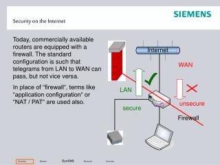
a) Core-based Monitoring In this method the ingress routers are used to copy the header of the incoming packets. The copy is decided by a pre-set probability parameter. The header is then used to create another packet, called the “probe packet”, recognizable by the egress router. The probe is made to follow the original’s path. The egress router calculates the delay. The loss ratio is done by computing the drop counts obtained from the core routers and the number of packets per flow obtained from the ingress routers. The throughput are obtained from the egress routers. 03-60-564 ci Fall04
b) Edgebased Monitoring The paper describes two edge-based monitoring methods: stripe-based and distributed. The delay and throughput are measured similarly to the core-based methods. The difference consists in measuring the loss ratio. i) Stripe-based Monitoring. This method is based on calculating the loss ratio using a special algorithm and not relying on the core routers. The algorithm consists in sending packets in groups of three, with no delay in between them. The groups are called stripes. To discuss this algorithm I will refer to Figure 2. 03-60-564 ci Fall04
The stripes are sent from source 0, through node k, to two destinations, R1 and R2, in a particular order. If the intend is to estimate the link k-R1, the first packet will be sent to R1 and the next two packets to R2. The probability of the loss for the link will be calculated based on how many packets reached their targets, R1 and R2 and in which order. Similarly will have to be done to estimate the loss of the k-R2 link, except that the first packet will sent to R2 and the next two to R1. To estimate the loss on 0-k link, the results from both above mentioned steps have to be considered. This method is explained in more details in [6], [9] and [11]. This method has been expanded in [11]. For complex trees, the stripes will be sent from the root to all the leaves of the tree and analyzed in a similar fashion as for the simple tree. 03-60-564 ci Fall04
ii) Distributed Monitoring. This method is based on network monitoring by an overlay network of SLA monitors. Figure 3(a) shows spanning tree of a domain configuration. The overlay network is shown in Figure 3(b). The internal links for each end-to-end path in the overlay network are shown in Figure 3(c). The delay and throughput measurements are the same as in stripe-based monitoring. Measuring loss is different. The monitors probe the network at certain intervals, until detect that a link has a higher loss than a specified threshold. The core of the method is to detect all the links with higher loss, called congested links. Every edge router probes its neighbors. If the measured loss is higher than the threshold in a link, a Boolean random variable Xp will change its value from 0 to 1. If the value is 0, then definitely all the internal links are notcongested. 03-60-564 ci Fall04
Figure 3. Network monitoring using the distributed mechanism. 03-60-564 ci Fall04
The advantage of using distributed monitoring scheme: • requires less number of total probes, O(n), compared to the stripe-based scheme, which requires O(n2); where n is the number of edge routers in the domain. • is capable to detect violation in both directions of any link in the domain. The stripe-based method can detect a violation only if the flow direction is the same between the probing direction from the root and the misbehaving traffic. To achieve the same ability like the distributed scheme, the stripe-based method needs to probe the whole tree from several points, which adds to the overhead considerably. 03-60-564 ci Fall04
3.Violation and DoS Detection Losses on guaranteed traffic class will flag an SLA violation. The first step in detecting DoS attacks is to identify a set of links with high loss. Let’s look at the Fig. 3. and consider that the victim’s domain D is connected to the edge router E6, and the congested links are C3 C4 and C4 E6 for a time Δt. The egress router E6 is the common denominator and the IP prefix of the destination proves that there is an excessive flow towards D. All what is needed at this point is for the monitor to identify the ingress routers of the attack and turn the filters on. This algorithm is treated in detail in [12]. The advantage of the monitoring-based attack detection is that the nearby domains might be able to flag an attack even before the victim will suffer, and this just by observing the SLA parameters. If the monitor will communicate with the hypothetical victim, different plans can be worked out to control the flow better. 03-60-564 ci Fall04
Ingress Filtering • Route-based packet filtering • Traceback with probabilistic packet marking • Core-based network monitoring • Stripe-based monitoring • Distributed monitoring Summary of the evaluation: • Filtering is a preventive method, prevents the attacks before they harm the system. • Traceback can only identify an attacker after the attack has occurred. • Marking requires less overhead than filtering, but is a forensic method. 03-60-564 ci Fall04
Ingress filtering has high implementation overhead as it needs to install filters at all ingress routers. • Core-based monitoring has high implementation overhead as it needs support from all edge and core routers in a domain. • Core-based scheme has less processing overhead than the stripe-based scheme because it aggregates flow information when it reports to the monitor. • The stripe-based monitoring scheme has lower communication overhead than the core-based scheme for relatively small size domains. • Core-based might need less communication overhead depending on the attack intensity for large domains. • The distributed scheme outperforms the other monitoring schemes in terms of deployment cost and overhead. 03-60-564 ci Fall04
Several methods to detect service level agreement violations and DoS attacks have been investigated. There are many methods available, but none to cover all the combinations. The attacker might confuse the victim by sending false ICMP traceback packets and by randomly marking attacking packets in ICMP traceback and probabilistic packet marking mechanisms. Ingress filters can only be effective if implemented at a very large scale. Route-based filters struggle in the area of the dynamic change of routing data. Network monitoring techniques are able to detect service violations by measuring the SLA parameters and also to early detect DoS attacks, decreasing the harm of the victim. The core of this is based on the fact that DoS attacks alter the flow parameters and monitoring the network flags congested links, and ultimately alert the victim and locate the attacker. 03-60-564 ci Fall04
II. The second paper presents mainly a mechanism to defend against distributed denial-of-service (DDoS) attacks where even if DDoS are considered congestion-control issues, to be handled by the routers. Each router has increased functionality to detect and drop packets identified as belonging to an attack. The term “pushback” comes from the fact that when a router identifies packets as part of an attack, it notifies the upstream routers as well to drop these packets and keep the router’s resources free to route good traffic. The paper presents the architecture, the implementation using FreeBSD and few suggestions about the pushback system implementation in core routers. 03-60-564 ci Fall04
The first part is a presentation of Distributed Denial of Service (DDoS) as in [MVS01]. What is being said differently from the first paper is that these attacks “are very hard to defend against because they do not target specific vulnerabilities of systems, but rather the very fact that the target is connected to the network”. The paper references Mahajan [MBF_ a, MBF_ b] who introduces the network-based solution, called “Pushback”, then presents the architecture of a router that can support it, followed by implementation and performance details. 03-60-564 ci Fall04
Similar to the first paper, the fact that routers are not able to just identify which flow is “good” or “bad” is being stated as well and is being introduced the concept of Aggregate-based Congestion Control (ACC) . An aggregate is defined as a subset of the traffic with an identifiable property. “Packets to destination D”, “TCP SYN packets”, or even “IP packets with a bad checksum” are examples of possible descriptions of aggregates. The goal is to identify aggregates causing the congestion and drop them at the routers. If we could surely identify packets as part of an attack, the case would be closed. 03-60-564 ci Fall04
Figure 1. A DDoS attack in progress. 03-60-564 ci Fall04
D is the destination. R1 to R8 are the last routers by which traffic reaches the destination. The thick lines are the links with bad traffic, and the thin lines are the links with good traffic. The last link, R8-D is congested, as non-attack traffic will not reach the destination. For the ease of explanation, the paper defines ‘good’, ‘bad’, and ‘poor’ traffic and packets. Badpackets are the packets sent by the attackers. Bad traffic is characterized by an ‘attack signature’. The attack signature is the common denominator that we want to find. The ‘congestion signature’ is the set of properties of the aggregate found as causing problems. ‘Poor’traffic is when the packets match the congestion signature, without being part of the attack, but they share the same destination or some properties. ‘Good’traffic has no resemblance with the congestion signature, but has common links with the bad traffic. 03-60-564 ci Fall04
A part of the traffic entering R2 is good (the part exiting R5 that is not going to R8), and a part is poor, as it is going to D. Similar to R4-R7 link. Depending on how congested the links R1-R5 and R2-R5 are, some good traffic entering R5 may suffer. R8 can do nothing to allow the good traffic to reach the destination. The single option is to drop all traffic from R5 and R6, which may as well be dropped at R5 and R6. This is done using Pushback, which communicates with the upstream link. In our case, Pushback sends packets to R5 and R6 instructing them to rate-limit traffic to D. The same will be done by R5 and R6 in regards to R1, R2 and R3. This way more good traffic will flow to the destination D. The rest of the paper describes the router architecture with its algorithm and its implementation using FreeBSD. 03-60-564 ci Fall04
Figure 2. Partial view of a router. 03-60-564 ci Fall04
The information send by the rate limiter to ‘pushbackd’ is shown in Figure 3. The magic number is for kernel and the user-level process synchronization. The timestamp along with the packet size, is to estimate the bandwidth possibly used by the dropped packets. The ‘reason’ field indicates if this was a tail-queue drop, a RED drop, etc. Only packets dropped because of queue discipline restrictions are logged; packets dropped because, for example, they were not routable, or no buffer space could be allocated for them at the driver may not even reach this part of the code, so they are not reported at all. To be noted is the separation of the rate limiting and packet dropping from the rest of the pushback mechanism. 03-60-564 ci Fall04
a) Aggregate Detection ‘Pushbackd’ analyzes the dropped packets received from rate limiter to detect congestion and determine if there is an attack. Various algorithms might be used, one can be found in [MBF_ a], the paper presents a different one. Let’s discuss our example and start with the set of packets dropped by the rate limiter. Very important feature is the algorithm to run in less time than it takes to collect the packets. The size of the drop set should be large enough to get some meaning out of it, but also small enough to be run in real time. To accomplish this the algorithm is sampling aggregates based on IP destination address only. It starts by analyzing if the congestion level is high enough. 03-60-564 ci Fall04
If the drop rate is high enough to do preferential dropping, the bandwidth Wo of the output link would be higher than an acceptable drop rate of 20% of the traffic, Wi-Wb>1.2xWo, and the algorithm will start by matching the destination address against the routing table. It will select the longest matching prefix. The dropped packets will be grouped based on their possible destination link. After that, the packets will be grouped again based on the prefix as the key, it will be sorted by the highest count. If after dropping same of the packets, the traffic doesn’t go below the acceptable level, which means Wi-Wb>1.2xWo still applies, the algorithm will be repeated with the hope of adding more prefixes to the congestion signature. 03-60-564 ci Fall04
b) Rate Limiting After finding the congestion signature, it must be decided the limit for the rate limiter. If Wb>Wl, where Wl=Wi-1.2xWo, the aggregate will be rate-limited down to Wl. The rest of the traffic will pass on. If Wb<Wl, all the traffic part of the congestion signature will be eliminated. The rest of the excess traffic will be limited by the output queue. The pushback daemon receives dropped packets from both, the rate limiter and the output queue. 03-60-564 ci Fall04
c) Pushback Pushback messages are described in detail in [FBI_ ]. There are three such messages: request, response, and status. Following is shown the pushback request. 03-60-564 ci Fall04
Rate-Limiting Session Identifier (RLS-ID): matches responses to requests. The Depth field: sets limit to propagation of pushback requests. The depth of originator is 0; upstream daemons add 1 to depth before propagating the message. The maximum depth of propagation is set by originating router, then passed along by the downstream routers. Pushback uses soft state; no explicit revocation of pushback request, no effort made to recapture the state after a router reset. The expiration time is used to manage this soft state – if Refresh message not received before expiration time elapsed, entry is deleted. The congestion signature is a list of destination prefixes that the bandwidth limit applies to. 03-60-564 ci Fall04
Authentication of Pushback requests is a serious concern. If routers participating in Pushback are located close to each other, sending the request out with a TTL of 255 is enough, considering that a request received from an attacker would have a lower TTL. A cancel message instructs the upstream router to stop rate-limiting. The Pushback daemon sends requests, and listens for requests from downstream routers as well. Once it receives a pushback request or refresh, it adds the most likely rule to the rate limiter, and keeps track of the dropped packets. In addition to requests sent upstream, the pushback daemon also sends status messages downstream. These status messages contain a depth field, which if non-zero, the response is passed downstream with 1 subtracted from the node depth. If depth is 0, it might use the contained information and consider if to continue the pushback. 03-60-564 ci Fall04
Mainly it states that DDoS attacks might be offset by using resource allocation techniques on network bandwidth. Integrated Services [CSZ92] and Differentiated Services [BBC_ 98] are two approaches meant at isolating flows with specific QoS requirements from low priority traffic. There are still few unknowns. First is if this method will suffice. Second, how far the compromised sources will go to hide it. [Van97] presented a similar approach to Pushback in an Active-Networks-based defense against flooding attacks. Many congestion-control mechanisms, already in existence, might ease some of the effects of congestion due to DDoS attacks if they were globally managed. 03-60-564 ci Fall04
Random Early Detect (RED)[FJ93] and its versions, Fair Queuing[DKS89], Class-Based Queuing[FJ95]) and many others packages have the same problem. Packets belonging to DDoS attacks do not have readily-recognizable flow signatures, and can not be identified by these schemes. The concept of Aggregate-based Congestion Control was developed[MBF_ c] for this reason. Combating DDoS attacks by prevention and detection methods presented in the first paper are captured in this paper as well. Not only the described methods are the same, but even the references. [Bel00] in this paper is [2] from the first paper. So are [BBC+98], [SWKA00], [BC00] from the first paper, [3], [21], [5] in the second paper. 03-60-564 ci Fall04
Pushback is more effective where the routers are relatively close to the target, which is most often the case on the Internet. It would be pretty hard for an attacker to ensure that the distribution of the slaves will be even distributed with respect to the target. It is known that Pushback looks promising in combating DDoS attacks and flash crowds from simulations [MBF_ c]. Situations apparently easy to simulate still need to be run and tested on real machines. Also to be determined is the memory needed and the computing power. 03-60-564 ci Fall04
Questions? 03-60-564 ci Fall04
Thank you! and Good Luck! 03-60-564 ci Fall04