Download
1 / 17
170 likes | 283 Views
Design and integration of HV, LED monitoring and calibration system for HCAL. Overview of the subsystems design High voltage system. LED monitoring system. Cs 137 radioactive source calibration system .

E N D
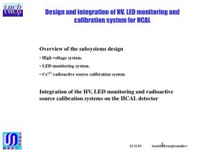
Design and integration of HV, LED monitoring and calibration system for HCAL Overview of the subsystems design • High voltage system. • LED monitoring system. • Cs137 radioactive source calibration system. Integration of the HV, LED monitoring and radioactive source calibration systems on the HCAL detector 21.11.03 Anatoli Konoplyannikov
Design and integration of HV, LED monitoring and calibration system for HCAL High voltage system The Cockcroft-Walton (CW) base for photomultipliers is used for LHCb calorimeters. The PMT chosen for the calorimeters is Hamamatsu photo-multiplier R7899-20. The CW solution has the following advantages over conventional passive divider and transistor bases: individual gain adjustment; efficient operation at high rate; low power dissipation; low voltage cabling and connectors reducing total cost. HCAL CW base circuit diagram. The HCAL high voltage (HV) system consists of: * about 1500 CW bases, those soldered on the PMT’s leads and placed in each cell of HCAL, * eight 216 – channels DAC boards for HV control voltage distribution, * three power supply units (+80 V, +- 6 V). The DAC boards are placed around the detector and the analogue HV control voltages are distributed to each base by a flat cable. 21.11.03 Anatoli Konoplyannikov
Design and integration of HV, LED monitoring and calibration system for HCAL High voltage system Oscillogram of a CW – base voltage ripple on dynode DY10 The gain deviation as function of the DC anode current for three gains 10^4, 10^5, 10^6. CW base main characteristics 21.11.03 Anatoli Konoplyannikov
Design and integration of HV, LED monitoring and calibration system for HCAL High voltage system The architecture of the subsystem is chosen taking into account following considerations: * The DAC ICs should be kept in a region with a lowest level of radiation. * The easy access for board exchange should be foreseen. * A cable length should be minimized in order to avoid a ground loop voltage shift. The board includes 200 channels of DAC integrated circuit for HV control and 16 channels for LED light intensity control. For readout of the control voltages, the multiplexers and ADC IC are used. An estimated power consumption is about 1.5 W per board and a board size is about 160*250 mm2. 216 – channels DAC board block diagram 21.11.03 Anatoli Konoplyannikov
Design and integration of HV, LED monitoring and calibration system for HCAL LED monitoring design The LED monitoring system is mainly aimed at: • a middle term monitoring of the PMT gain stability, • an ADC sample time calibration and adjustment Sketch of the optical part of the LED monitoring system The LED monitoring system consists of four functional parts: • optical mixer and light distribution fibers, • LED driver with LED and PIN diode with amplifier for a LED light stability monitoring. The PIN diode signal after amplification is sent to the LFB front-end electronics board. • light intensity control board with DACs , • LED triggering pulse distribution board. 21.11.03 Anatoli Konoplyannikov
Design and integration of HV, LED monitoring and calibration system for HCAL LED monitoring design The dedicated HCAL versions of the LED driver and PIN diode amplifier were developed. The main LED driver features are: controlled light intensity edge sensitive triggering overshot circuit allows to decrease the trailing edge of a light flash dimension of the printed board is 40*70 mm*mm mechanical design is optimised for HCAL LED driver block diagram 21.11.03 Anatoli Konoplyannikov
Design and integration of HV, LED monitoring and calibration system for HCAL LED monitoring design LED PIN diode Photo of the light mixer with LED driver and PIN diode amplifier printed circuit boards 21.11.03 Anatoli Konoplyannikov
Design and integration of HV, LED monitoring and calibration system for HCAL LED monitoring design 50 Gev pions LED signal Oscillograms of the 50 Gev pions signals and LED signals for clipped and non-clipped cases. Signal clipped on 1.2 m coax with 22 Ohm termination Comparison the signal shape for 50 GeV pions and LED signal 21.11.03 Anatoli Konoplyannikov
Design and integration of HV, LED monitoring and calibration system for HCAL LED monitoring design For LED trigger pulse distribution a 64 – channels dedicated board has to be developed. It will be placed in to the spare slot of the 9U LFB crate. This crate is connected to TTC and ECS systems. Synopsis of LED Trigger Board (LEDTB) 21.11.03 Anatoli Konoplyannikov
Design and integration of HV, LED monitoring and calibration system for HCAL 137Cs radioactive source calibration system System overview The reliable and stable calibration method has been developed and tested with HCAL Prototype. Its aim is to monitor the detector properties, like ageing of plastic and fibers, and give an absolute reference for the cell calibration. The radioactive 137Cs gamma-source that has 30 years half-life is used. Three sources encapsulated in the stainless steel pipe were obtained, with activities of 5, 8 and 10 mCi. The HCAL calibration system incorporates the following parts: • continuous 8 mm diameter stainless steel pipe that is fed through the middle of all scintillating tiles and filled with a distilled water; • a computer controlled hydraulic pump and valves that create a reversible water flow in the pipe and therefore move the capsule with a radioactive source throughout the detector; • an automated garage with a 5 cm thick lead wall, to safely keep the source between calibration runs; • integrated on-detector electronics to measure the PMT current when the source is moved from cell to cell across the HCAL. 21.11.03 Anatoli Konoplyannikov
Design and integration of HV, LED monitoring and calibration system for HCAL PMT anode current produced by radioactive source is integrated by an electronic integrator with a decay time of order of 2 msec. Readout board collects analog signal from one module phototubes, digitizes them and stores into a local memory (it takes 125 sec/module). Then the data are transferred to a computer through CAN bus interface (it takes about 4 msec). The readout continues till the source run through the module. Two or five 8 - channel integrator boards (placed into the module) and 520 – channel readout board (placed on the detector) have been developed. Photo of the 8 – channels integrator and readout boards 21.11.03 Anatoli Konoplyannikov
Design and integration of HV, LED monitoring and calibration system for HCAL 6U VME size crate for control and monitoring electronics Garage for radioactive source storage crate with hydraulic apparatus Photo of the rack with the hydraulic and control electronic crates 21.11.03 Anatoli Konoplyannikov
Design and integration of HV, LED monitoring and calibration system for HCAL PMT with CW base Integration of the HV, LED monitoring and radioactive source systems on the HCAL detector. Placement of the electronic boards and connection with ECS The electronic boards of mentioned systems will be placed partially into the HCAL modules and around the detector. There are two options for the board integration on the detector. Main option is the electronics placement on the top and bottom platforms. In this case one has easy access to all boards, but the cable length of the analog control signals is not minimal. Another option is to distribute the boards on the side of detector. In this case the cable length is minimal, but the access is less convenient. Photo of the internal cabling and CW base integration into HCAL module 21.11.03 Anatoli Konoplyannikov
Design and integration of HV, LED monitoring and calibration system for HCAL 2 or 5 (16 or 40 channel HCAL module) 8 contact coax connectors for connection with Front-End crate 5 pin connector for PIN diodes and LED triggering signals 2 of 10 pin connectors for CW base and LED power supply 34 pin connector for Cs calibration system 2 of 40 pin connectors for HV control signals HCAL module side panel with connectors 21.11.03 Anatoli Konoplyannikov
Design and integration of HV, LED monitoring and calibration system for HCAL LFB rack with crates The estimated cross-sections of the cables integrated on the HCAL side are following: • coax cables cross-section is about 120 * 120 mm2, • flat cables cross-section is about 70 * 100 mm2. LED triggering Board connected to TTC and ECS 6U VME size crate for Cs source monitoring,and control electronics Garage 33 * 40 wire flatcable 850 coax cables of 3 mm diameter Two boards of HV and LED DAC control voltage + one board of Integrators Readout connected to ECS Sketch of the electronic boards and crates integration on the HCAL detector Crate with hydraulic apparatus 21.11.03 Anatoli Konoplyannikov
Design and integration of HV, LED monitoring and calibration system for HCAL The list of the half HCAL electronic boards integrated outside of the detector 21.11.03 Anatoli Konoplyannikov
Design and integration of HV, LED monitoring and calibration system for HCAL Procedure of the PMTs assembly and cabling + needed manpower • 1500 PMTs and CW base assembly – 3 man-weeks • 1500 PMT + CW base test and Gain vs HV measurement – 6 man-weeks • 44 sets of coax and flat cables preparation and installation inside HCAL – 8 man-weeks • 1500 PMT + CW base installation into modules– 3 man-weeks 21.11.03 Anatoli Konoplyannikov