B550 (PN**B550T2FXZA)
1.05k likes | 1.64k Views
PDP TV Training Manual. B550 (PN**B550T2FXZA). Agenda. Inside of B550 New Feature Board descripton Disassembly Trouble Shooting. I . Inside of B550. Inside of B550. I . Inside of B550. I . Inside of B550. I . Inside of B550. I . Inside of B550. Spec Comparison. I . Inside of B550.

B550 (PN**B550T2FXZA)
E N D
Presentation Transcript
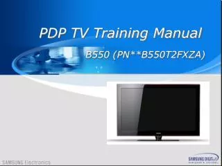
PDP TV Training Manual B550 (PN**B550T2FXZA)
Agenda • Inside of B550 • New Feature • Board descripton • Disassembly • Trouble Shooting
I. Inside of B550 Inside of B550
I. Inside of B550 Spec Comparison
I. Inside of B550 Control & Connection Panel
I. Inside of B550 Control & Connection Panel (TV,AV1,AV2,S-VIDEO,Component1,Component2,PC ,HDMI1,HDMI2/DVI,HDMI3,HDMI4,USB)
I. Inside of B550 Control & Connection Panel
I. Inside of B550 Control & Connection Panel
I. Inside of B550 Control & Connection Panel
I. Inside of B550 Control & Connection Panel
I. Inside of B550 Control & Connection Panel
I. Inside of B550 Control & Connection Panel
I. Inside of B550 Control & Connection Panel
I. Inside of B550 Control & Connection Panel
I. Inside of B550 Control & Connection Panel
I. Inside of B550 Control & Connection Panel
I. Inside of B550 Remote control
I. Inside of B550 CN5401 Y-BUFFER(UP) U4004 CN803 CN4000 CN5400 CN5005 SMPS - DC CN804 CN5404 CN5402 CN4002 CN5403 CN805 CN5001 CN5405 CN800 CN802 Y-MAIN CN801 CN5505 CN4004 CN5503 CN5502 CN5501 CN2008 CN4006 CN4501 CN2001 CN2010 CN5002 CN5510 X-MAIN CN5500 CN2002 CN2015 LOGIC BOARD CN2000 CN4502 CN2006 CN2007 CN5502 Y-BUFFER(LOW) G-BUFFER E-BUFFER CN2514 CN2508 CN2509 CN2500 CN2701 CN2700 CN1103 CN101 AC-INLET SPEAKER CN1501 CN801 IR Wiring Diagram cn1501
I. Inside of B550 HALF NIM TU SATURN4 ATSC Block Diagram – PDP SATURN4 MSD3003 S5H1411 TUNER_TS USB2.0 USB2.0 TS0 IN USB (Wise Link / Download) TU_SIF DDR2 IF DDR2-400 64MB DDR2 I/F HDMI_OPT HDMI opt 550 only OTA opt HDMI1 HDMI RXA SYNC mode SPI FLASH 8MB HDMI SW TMDS361 SPI HDMI2 HDMI RXB SIDE HDMI3 Small LCD HDMI Path (Auto Wall / Debug) HDMI RXC UART_WALL_DEBUG HDMI 1,2,3 UART UART SP3232 UART_HOTEL UART TUNER_CVBS UART CVBS0 COMP1(VIDEO1) IR, Key CVBS3 COMPONENT 1 (VIDEO 1) IR, Key INPUT COMP1(VIDEO1) RGBIN0 EEPROM 24C512 Display Panel COMPONENT 2 COMP2 RGBIN2 LVDS_HD(FHD)_60Hz LVDS_OUT PC_RGB/H/V RGBIN1 PC PC Audio SIDE_CVBS CVBS1 SPK I2S_S4 SOUND AMP NTP3200 I2S_OUT SIDE SIF_TU SIFP/M COMP(V1)1_L/R SPDIF AULR0 SPDIF Out SPDIFO COMP2_L/R AULR1 DACOUT0 PC_L/R AULR2 MON_L/R_OUT MON AMP TL062CDT SIDE_L/R LINE_OUT1 AULR5 MONITOR Out SIDE VIDEO 2
I. Inside of B550 SATURN4 ATSC VIDEO DECODER BLOCK DIAGRAM
I. Inside of B550 VIDEO IN-OUT PATH 550 OPTION D1 LVDS option : A-ODD, B-EVEND2 LVDS option : B-ODD, A-EVEN
I. Inside of B550 AUDIO IN & OUTPUT Path
I. Inside of B550 I2C TREE SCL_TU/SDA_TU DDCR_CK DDCR_DK S5H1411 TUNER (R:0xC1, W:0xC0) SCL_EEP/SDA_EEP AT24C512BN ( R: 0xA1, W: 0xA0 ) GPIO60 GPIO62 SCL_D/SDA_D NTP3200 (R0x55,W:0x54) GPIO61 GPIO59 SCL_PANEL/SDA_PANEL GPIO85 GPIO84 PANEL (0x) AT24C02 ( R: 0xA1, W: 0xA0) AT24C02 (0xA0) I2C_HDMI (for DDC) AT24C02 (0xA0) I2C_PC (for DDC & ISP) AT24C02 ( R: 0xA1, W: 0xA0)
I. Inside of B550 UART TREE ZIC701 ZIN703 MSD3003 RXD_HOTEL IS2S_OUT_MUTE GPIO56 SN74LVC1G TXD_HOTEL DBG_WALL_TX IC701 UART2_TX UART2_RX SP3232 DBG_WALL_RX Wall/DEBUG TC7WB125 PDP_Only SCL_PANEL RX2/DDCA_CLK TX2/DDCA_DA PANEL Level shift SDA_PANEL DDC SELF WRITE IC903 AT24C02N COM_LOGIC_TXCK RX0/DDCA_CLK TX0/DDCA_DA PC-JACK COM_LOGIC_TXDA
I. Inside of B550 POWER TREE PDP D1 (REGULATOR 別-선행) RT9818/SP3232EEY IR & Function EEPROM/Serial FLASH A3.3V 340mA IC106 AP1117D IC201 MSD3003 A1.26V 940mA IC107 AOZ1021 AB5V A5V IC505 AP1117D Q108 SI3443BDV A5V_S4 A5V #4 DDR1.9V 500mA 270mA IC202 DDR2-64M 167mA(ON) 61mA(STB) B5V #13~16 B5V USB/OPTICAL 905mA B3.3V 186mA IC109 AP1117D IC602 S5H1411 TU1.2V 100mA IC601 AP1117D IC103 NTP3200 B1.8V B15V_AMP B15VS #7,8 63mA/Max:1.25A IC105 BA178M09 IC110 KIA7805AF B15V B9V 210mA TU5V B15V #20~22 200mA Slim Half Tuner 254mA IC603 TU33V IC101 TL062CDT(M OUT)
I. Inside of B550 POWER SEQUENCE-50” FHD PDP(DANAM Rev0.61/081014) Power Off Power On Master On 2nd Power Detection STB_5V 220ms *Assert High by RT9818 automatically, after master on. *RT9818 keep low status during 220 ms after power on. 45ms CPU_nRESET (HWRESET) SPEC: Min 30ms이상유지 600ms *Shall be kept High status after master on. (need logic reset time) *Assert High signal if an "On" command is received through IR or Key input. SW_POWER (GPIO_PM1) 61ms 2nd Power (B+) 220ms *Dependant on RT9818 delay. POWER_DET (GPIO_PM6_INT2) *Device Reset Period [S5H1411] 2.65S *Assert High when system ready. NRESET_TU (GPIO94) *Device Reset Period [NTP3200] 4.05S *Assert High when system ready. AMP_RESET (GPIO86) 3.1S LVDS_Out
I. Inside of B550 Adjust SMPS Voltage when change SMPS Vs Adjustment Vs Test Point Va Test Point VE Va Adjustment
Ⅱ. New Feature of B550 New Feature Of B550
Ⅱ. New Feature of B550 New Feature(600Hz Subfield Motion) Removes drag from fast scenes with a lot of movement to provide a clearer picture.
Ⅱ. New Feature of B550 New Feature(600Hz Subfield Motion)
Ⅱ. New Feature of B550 TruSurround HD VS. TruSurround XT
Ⅲ. Board Description BOARD DESCRIPTION
Ⅲ. Board Description USB2.0 CN803 LVDS 51p Box FHD LVDS 51p FPCB FHD LVDS 31p FFC HD PC LR IN 1411 CH CN904 3722-001061 Function CN702 DDR Flash 512M Flash 512M NTP3200 sound CN101 24P 3711-006766 CN805 Side AV 3722-002543 3722-002697 SATURN4 PDP PCB LAYOUT (192x158, 4L, Normal) 192 75 30 30 POWER CN102 SPK 3711-00001 HDMI4 CN802 3701-001388 A D D A D T R A D D A D T R 158 PC RGB IN USB CN701: 3722-002516 TU601 ATSC HALF HDMI2 CN902 3701-001367 CN903 3701-001480 150 OP701 3707-001081
Ⅲ. Board Description Main board connector pin map
Ⅲ. Board Description Main board connector pin map
Ⅲ. Board Description SMPS BOARD(50”)
Ⅲ. Board Description SMPS BOARD(58”/63”)
IV. Disassembly DISASSEMBLY
IV. Disassembly ASSY STAND P-BASE
IV. Disassembly ASSY COVER P-REAR 5
IV. Disassembly FILTER-EMI AC LINE 3
IV. Disassembly BRACKET P-PCB
IV. Disassembly ASSY BRACKET P-SUPPORT STAND
IV. Disassembly ASSY BRACKET P-SUPPORT FILTER
IV. Disassembly SMPS-PDP TV
IV. Disassembly ASSY PDP MODULE P-LOGIC MAIN BOARD
IV. Disassembly ASSY PDP MODULE P-X MAIN BOARD