Download
1 / 43
430 likes | 698 Views
Heavy Lift Cargo Plane Progress Presentation. Matthew Chin, Aaron Dickerson Brett J. Ulrich, Tzvee Wood. November 4 th , 2004 Group #1 – Project #3. Presentation Outline. Review of Project Objectives & Deliverables Early Design Concepts Computer Software Implementation Data Digitalization

E N D
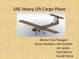
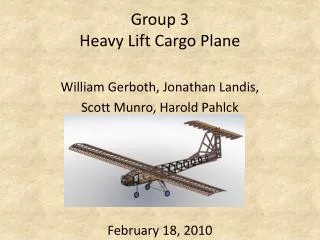
Heavy Lift Cargo Plane Progress Presentation Matthew Chin, Aaron Dickerson Brett J. Ulrich, Tzvee Wood November 4th, 2004 Group #1 – Project #3
Presentation Outline • Review of Project Objectives & Deliverables • Early Design Concepts • Computer Software Implementation • Data Digitalization • WINFOIL Evaluations • Engineering Equation Solver Calculations • Design Concepts • Wing • Landing Gear • Tail • Prop • Schedule Update
Project Objectives • Compete in SAE Aero East Competition • Apply areas of Mechanical Engineering education to a real life problem: • Dynamics • Fluid Mechanics • Modeling & Simulation • Analysis of Stresses
Project Objectives • Dynamics/Analysis of stresses Force of drag, weight, and gravity on the wing/fuselage • Fluid Mechanics Used in analysis of airfoil • Modeling & Simulation For CAD models of wing, fuselage, landing gear
Anticipated Deliverables • Finished calculations • Final wing selection • Sketches of the final design • CAD drawings - wing, fuselage, landing gear • Projected construction budget • Parts order
Problems To Watch Out For • Ideal design needs to be able to be actually constructed • Stability of construction so that the plane does not fall apart on landing • Time management for construction • Previous team only used one design did not iterate • More practice on shrink wrap coating procedure for wing
Early Design Concepts • Biplanes originally popular for increased lifting capacity • At this scale the effect of the additional wing is not worth the additional weight and construction cost
Early Design Concepts • Dual wing plane also considered • Initially thought to be able to produce significantly more lift than standard monoplane • Alignment of wings can produce major parasitic losses if done improperly
Early Design Concepts • Flying wing early popular concept • One large wing has significantly larger area than standard monoplane • Possibly difficult to build and transport • Still under consideration
Data Digitalization • SAE Documentation Provides Data for LMN-1 Airfoil (similar to Selig 1223, Liebeck LD-X17A and other RC aircraft) • Data includes: • The dependence of CL on Aspect Ratio and Angle of Attack • Viscous drag due to lift • Ratio of Thrust to Static Thrust vs. Speed
Data Digitalization • The following graphs are provided in the aforementioned white paper
Data Digitalization manually • Large samples of data points were recorded and entered into MATLAB In the event you missed it, they’re computerized now!
Wing AnalysisWith WINFOIL • Monoplane first examined • First sought to examine the effects of different designs on L/D Ratio: • Constant Chord • Tapered • Swept Back Tapered • For each design L/D ratio is the same • Can be easily seen from CL αCD • CL=L/(0.5*AP*V2*ρ) • CD=D/(0.5*AP*V2*ρ)
Wing AnalysisWith WINFOIL • Selected Eppler 193 Mod Wing • Previous designs • Suggestion of Senior Design Coordinator • Higher CL than other airfoils such as NACA 6409 • Relatively easy to build • No fine trailing edge • Reasonable Thickness • Decided against use of Swept Back Tapered • Too many variables • Requires too much precision • Tapered Wing is still under consideration
Wing AnalysisWith WINFOIL • Effect of wing taper ratio on various performance characteristics examined • Assumptions: • Wing holds entire plane weight assumed to be 7lbs • Max 2hp • No fuselage accounted for
Wing AnalysisWith WINFOIL • Flying Wing Analysis • Like the Monoplane L/D ratio is independent of wing design for wings of same area
Wing AnalysisWith WINFOIL • WINFOIL 3D Rendering • Still experiencing problems exporting from WINFOIL to CAD programs for tapered wings
Wing Features Being Considered • Hoerner Plates – reduce tip losses • Dihedral Angle – reduces chance of stall under banked conditions May not be necessary for a 60” wingspan
Add’l Computer Analysis • Previously generated MATLAB curve fits utilized in EES for calculations • Entire current EES model included in presentation handouts
Add’l Computer Analysis • Based upon white paper and aerodynamic principles • Input Design Parameters • Takeoff distance (e.g., <190ft) 28 ft • Landing Distance (e.g., <380ft) 46 ft • FuselageLength 10 in • FuselageWidth 5 in • FuselageBoomLength 40 in • WingSpan 60 in • WingAR 1.62 • WingTaper 1.0 • S_Ref 1800 in2
Add’l Computer Analysis • Output Values • Takeoff velocity 48 ft/s = 33 mph • Stall velocity 49 ft/s = 34 mph • Maximum weight (plane + payload) • Next generation of EES development • Currently Weight is an input • Benefits • Rapid design • Reduced chance for calculation errors • Continuous refinement - design called for and time permitted • Reusable in future years
Add’l Computer Analysis • Mathematical analysis entered into to EES
Add’l Computer Analysis • Mathematical analysis entered into to EES
Landing Gear • Tricycle • Conventional Tail Dragger • Tandem
Landing Gear • Tail dragger • Only uses two forward main wheels • Reduces weight • Reduces drag • May be unstable when aircraft turns • Tricycle • Three wheel configuration • Increases control on ground if equipped with steerable front wheel • Tandem usually used on large aircraft
Landing Gear • Landing gear week point in past designs • CAD Model for Conventional Landing Gear Primary Assembly • Aluminum support • Nylon wheels
Landing Gear • Simulate impact of a 30lbs plane dropping from a stall • Applied 80lbs to the surface simulating attachment to the plane
Other Plane Features • Boom length – too long can create increased drag and instability • Vertical stabilizer height – if too large, the control surface induces a large moment leading to instability Led to a crash in 2002
Tail Design • Vertical Stabilizer • Single • Dual Configuration
Tail Design • Stabilizer/Elevator • Fixed Stabilizer Portion • Moveable Elevator • Requires complex mechanism to move elevator • Increases drag if not trimmed for the specific cruising speed of the aircraft • Stabilator • Serves double duty as a stabilizer and elevator • Rotates on aerodynamic center • Mechanism to rotate stabilator will be less complex than required for stabilizer/elevator • Theoretically reduces drag • Generally used in very fast aircraft
Prop Selection • Propeller selection depends upon the size of the engine • Propeller will be purchased from outside source • Precise dimensions difficult to manufacture by hand • Higher grade materials with higher strength to weight ratio available commercially
Prop Selection • Competition rules mandate use of a O.S. .61 FX engine • 0.607 cu in displacement • Manufacturer recommends the following props: • 11x8-10 • 12x7-11 • 12.5x6-7
Prop Selection • Dynathrust Props (www.dynathrustprops.com) sells injection molded fiberglass and nylon propellers • Higher strength to weight ratio than wood props • Prop manufacturer reccomends the following props: • 11x7-8 • 12x6 • A 12x8 prop costs only $3.00 • Manufacturing labor time cost will also be saved
Materials • Balsa wood • Injection molded fiberglass and nylon • Light metal, such as aluminum • Heat shrink monocoat for wing • Rip-stop Nylon • Carbon fiber tubing
Conclusions • Digitalized data enables swift calculations in EES • Design team has evaluated past difficulties • Wing design is on schedule • Select final wing profile • Select monoplane or flying wing • Landing gear will be selected when plane design is finalized • Monoplane = Conventional Tail Dragger • Flying Wing = Tricycle • Tail will consist of a single vertical stabilizer, exact shape to be determined when wing design is complete • Prop will be outsourced to save time and money
We Welcome Your Questions and Feedback Thank You
References • http://students.sae.org/competitions/aerodesign/east • http://adg.stanford.edu/aa241/performance/landing.html • http://adg.stanford.edu/aa241/wingdesign/wingparams.html • http://www.profili2.com/eng/default.htm • http://www.uoguelph.ca/~antoon/websites/air.htm • http://www.angelfire.com/ar2/planes2/links.html • http://www.geocities.com/CapeCanaveral/Hall/2716/index.html • http://www.winfoil.com/