Download
1 / 34
340 likes | 441 Views
Explore the integration of Adaptive Mesh Refinement in Particle-In-Cell simulations for inertial fusion, addressing scale challenges and grid asymmetries. Learn about electrostatic and electromagnetic applications and the impact of algorithm selection on accuracy.

E N D
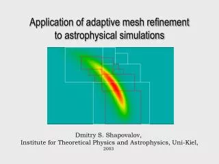
Application of Adaptive Mesh Refinement to PIC simulations in inertial fusion J.-L. Vay, P. Colella, J.W. Kwan, P. McCorquodale, D. Serafini Lawrence Berkeley National Laboratory A. Friedman, D.P. Grote, G. Westenskow Lawrence Livermore National Laboratory J.-C. Adam, A. Héron CPHT, Ecole Polytechnique, France I. Haber University of Maryland 15th International Symposium on Heavy Ion Inertial Fusion Princeton, New Jersey June 7-11, 2004
Outline • Motivations for coupling PIC with AMR • Issues • Examples of electrostatic and electromagnetic PIC-AMR • Joint project at LBNL to develop AMR library for PIC • Conclusion
Goal: end-to-end modeling of a Heavy Ion Fusion driver challenging because length scales span a wide range: mm to km(s)
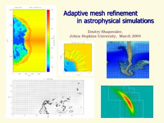
The Adaptive-Mesh-Refinement (AMR) method • addresses the issue of wide range of space scales • well established method in fluid calculations 3D AMR simulation of an explosion (microseconds after ignition) AMR concentrates the resolution around the edge which contains the most interesting scientific features.
Mesh Refinement in Particle-In-Cell: Issues • Asymmetry of grid implies asymmetry of field solution for one particle • spurious self-force • Some implementations may violate Gauss’ Law • Total charge may not be conserved exactly • EM: shortest wavelength resolved on fine grid not resolved on coarse grid reflect at interface with factor>1 • May cause instability by multiple reflections As shown in the following slides, the choice of algorithm matters.
“Mother” grid Patch grid Electrostatic: possible implementations • Given a hierarchy of grids, there exists several ways to solve Poisson • Two considered: • ‘1-pass’ • solve on coarse grid • interpolate solution on fine grid boundary • solve on fine grid • different values on collocated nodes • ‘back-and-forth’ • interleave coarse and fine grid relaxations • collocated nodes values reconciliation • same values on collocated nodes
one particle attracted by its image Metallic boundary “Mother” grid Patch grid zoom Test particle Spurious “image” particle trapped in patch • MR introduces spurious force, Illustration of the spurious self-force effect • 2-grid set with metallic boundary; as if there was a spurious image
1-pass multipass Log(E) Linear y Quadratic x Self-force amplitude map and mitigation main grid patch transition region • Magnitude of self force decreases rapidly with distance from edge • with the 1-pass method, the self-force effect can be mitigated by defining a transition region surrounding the patch in which deposit charge and solve but get field from underlying coarse patch
Electromagnetics: usual scheme Rf P Rc: coarse resolution Rf: fine resolution Rc G • the solution is computed as usual in the main grid and in the patch • interpolation is performed at the interface • unfortunately, most schemes relying on interpolations have instability issues at short wavelengths (the ones that may be generated in the patch but cannot propagate in the main grid)
Illustration of instability in 1-D EM tests o: E, x:B Space only Space+Time
Electromagnetics: we proposed a method by “substitution” Rf ABC P2 Outside patch: F = F(G) Rc P1 Inside patch: F = F(G)+F(P2)-F(P1) Rc: coarse resolution Rf: fine resolution Rc G
3D WARP simulation of High-Current Experiment (HCX) Modeling of source is critical since it determines initial shape of beam WARP simulations show that a fairly high resolution is needed to reach convergence
Medium res. Medium res. Low res. Low res. Medium res. +MR Medium res. +MR High res. High res. Prototype MR implemented in WARPrz (f axisymmetric ) • Three runs with single uniform grid • One run at medium resolution + MR patch In this case: speedup ~ 4
Medium res. Low res. Medium res. Low res. Medium res. +AMR High res. Medium res. +AMR High res. Prototype AMR implemented in WARPrz (f axisymmetric ) • Better results obtained with a dynamic AMR mockup refining emitter area + beam edge In this case: speedup ~ 4 In this case: speedup ~ 4
Low res. +AMR zoom (Ntransit=2) R (m) Low res. +AMR Z (m) (Ntransit=0) Z (m) Z (m) Refinement of gradients: emitting area, beam edge and front. Prototype AMR implemented in WARPrz (2) • Higher speedup obtained with a “true” dynamic AMR implementation R (m) Medium res. Low res. Z (m) High res. In this case: speedup ~ 11.3
3D WARP simulation of HCX shows beam head scrapping Rise-time t = 800 ns beam head particle loss < 0.1% x (m) z (m) Rise-time t = 400 ns zero beam head particle loss x (m) • Can we get even cleaner head with faster rise-time? • Optimum? z (m)
di virtual surface current time Vi irregular patch in di irregular patch in di + AMR following front “L-T” waveform N = 160 Dt = 1ns d = 0.4m Ns = 200 AMR ratio = 16 I (A) dx0/Dx~10-5! Time (s) Time (s) Time (s) 1D time-dependent modeling of ion diode: fast rise-time Irregular MR patch covering emission area suppresses long wavelength oscillation Adaptive MR patch following the beam head suppresses front peak Emitter Collector d V V=0 Careful analysis shows that di too large by >104 => irregular patch Insufficient resolution of beam front => AMR patch
Application to three dimensions • Specialized 1-D patch implemented in 3-D injection routine (2-D array) • Extension Lampel-Tiefenback technique to 3-D implemented in WARP • predicts a voltage waveform which extracts a nearly flat current at emitter • Without MR, WARP predicts overshoot • Run with MR predicts very sharp risetime (not square due to erosion) STS500 experiment “Optimized” Voltage Current at Z=0.62m X (m) V (kV) Z (m) T (ms)
No MR With MR Current history (Z=0.62m) Current history (Z=0.62m) Z (m) Comparison with experiment • Experimental voltage lowered so that risetime = particle transit time • Mesh Refinement essential to recover experimental results • Ratio of smaller mesh to main grid mesh ~ 1/1000
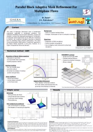
Patch 2s=28/k0 core Laser beam l=1mm, 1020W.cm-2 (Posc/mec~8,83) 10nc, 10keV Laser-plasma interaction in the context of fast ignition • A laser impinges on a cylindrical target which density is far greater than the critical density. • The center of the plasma is artificially cooled to simulate a cold high-density core. • Patch boundary surrounds plasma. Laser launched outside the patch. • Implemented new MR technique in EM PIC code Emi2d (E. Polytech.)
same results except for small residual incident laser outside region of interest (well understood, possible cures) Comparison single uniform high res. grid / low res. + patch • no instability nor spurious wave reflection observed at patch border without patch • can be used as is for various applications and we are also exploring improvements and variants with patch
Effort to develop AMR library for PIC at LBNL • Researchers from AFRD (PIC) and ANAG (AMR-Phil Colella’s group) collaborate to provide a library of tools that will give AMR capability to existing PIC codes (on serial and parallel computers) • The base is the existing ANAG’s AMR library Chombo • The way it works • WARP is test PIC code but library will be usable by any PIC code
Example of WARP-Chombo injector field calculation • Interactions with particles is being implemented
Conclusion • PIC and AMR are numerical techniques that have proven to be very valuable in various fields and their combination may lead to more powerful tools for beams and plasmas modeling in inertial fusion (and beyond). • The implementation must be done with care (beware of potential spurious self-forces, violation of Gauss’ Law, reflection of smallest wavelengths). • Prototypes of AMR methods were implemented in existing PIC codes and test runs demonstrated the effectiveness of the method in ES-PIC and a proof-of-principle of a new method was performed in EM-PIC. • There is an ongoing effort at LBNL to build an AMR library which will ultimately provide AMR capabilities to existing PIC codes.
In driver -12 -11 -10 -9 -8 -7 -6 -5 -4 -3 -2 -1 0 In chamber Time and length scales in driver and chamber span a wide range Time scales: depressed betatron betatron t electron drift pb out of magnet » transit lattice thru electron period fringe beam cyclotron pulse fields residence in magnet log of timescale pulse beam t pe in seconds residence t pi t pb Length scales: • electron gyroradius in magnet ~10 mm • lD,beam ~ 1 mm • beam radius ~ cm • machine length ~ km's
Back and forth 1 pass Back and forth y Linear y x Quadratic x x Global error • global error larger with BF than 1P • BF: Gauss’ law not satisfied; error transmitted to coarse grid solution
Electrostatic issues: summary • Mesh Refinement introduces spurious self-force that has a repulsive effect on a macroparticle close to coarse-fine interface in fine grid, but: • real simulations involve many macroparticles: dilution of the spurious force • for some coarse-fine grid coupling, the magnitude of the spurious effect can be reduced by an order of magnitude by interpolating to and from collocated nodes in band in fine grid along coarse-fine interface • we may also simply discard the fine grid solution in band and use coarse grid solution instead for force gathering (or ramp) • some scheme may violate Gauss’ law and may introduce unphysical non-linearities into “mother” grid solution: hopefully there is also dilution of the effect in real simulations • we note that our tests were performed for a node-centered implementation and our conclusion applies to this case only. For example, a cell-centered implementation does strictly enforce Gauss’ Law and results may differ.