Overview of Image-Based Rendering Techniques and Their Applications
This presentation introduces Image-Based Rendering (IBR) as a solution to the challenges of complex scene rendering, focusing on its potential for interactive visualization of large scientific datasets. It covers various IBR methods, including Plenoptic Modeling, Light Field Rendering, QuickTime VR, and Concentric Mosaics, highlighting their principles, advantages, and limitations. The discussion emphasizes how IBR efficiently uses a set of images from predefined viewpoints to generate new views, significantly reducing computational complexity without compromising image quality.

Overview of Image-Based Rendering Techniques and Their Applications
E N D
Presentation Transcript
Introduction to Image-Based Rendering Lining Yang yangl1@ornl.gov A part of this set of slides reference slides used at Standford by Prof. Pat Hanrahan and Philipp Slusallek.
References: • S. E. Chen, “QuickTime VR – An Image-Based Approach to Virtual Environment Navigation,” Proc. SIGGRAPH ’95, pp. 29-38, 1995 • S. Gortler, R. Grzeszczuk, R. Szeliski, and M. Cohen, “The Lumigraph,” Proc SIGGRAPH ’96, pp. 43-54, 1996 • M. Levoy and P. Hanrahan, “Light Field Rendering,” Proc. SIGGRAPH ’96, 1996. • L. McMillan and G. Bishop, “Plenoptic Modeling: An Image-Based Rendering System,” Proc. SIGGRAPH ’95, pp. 39-46, 1995 • J. Shade, S. Gortler, Li-Wei He, and R. Szeliski, “Layered Depth Images,” Proc. SIGGRAPH ’98, pp 231-242, 1998 • Heung-Yeung Shum, Li-Wei He, “Rendering With Concentric Mosaics,” Proc. SIGGRAPH ’99, pp. 299-306, 1999
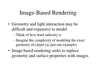
Problem Description • Complex Rendering of Synthetic Scene takes too long to finish • Interactivity is impossible • Interactive visualization of extremely large scientific data is also not possible • Image-Based Rendering (IBR) is used to accelerate the renderings.
Examples of Complex Rendering Povray quaterly competition site March – June, 2001
Examples of Large Dataset LLNL ASCI Quantum molecular simulation site
Image-Based Rendering (IBR) • The models for conventional polygon-based graphics have become too complex. • IBR represents complex 3D environments using a set of images from different (pre-defined) viewpoints • It produces images for new views using these finite initial images and additional information, such as depth. • The computation complexity is bounded by the image resolution, instead of the scene complexity.
Image-Based Rendering (IBR) Mark Levoy’s 1997 Siggraph talk
Overview of IBR Systems • Plenoptic Function • QuicktimeVR • Light fields/lumigraph • Concentric Mosaics • Plenoptic Modeling and Layered Depth Image
Plenoptic Function • Plenoptic function (7D) depicts light rays passing through: • center of camera at any location (x,y,z) • at any viewing angle ( , ) • for every wavelength ( ) • for any time ( t )
Limiting Dimensions of Plenoptic Functions • Plenoptic modeling (5D) : ignore time & wavelength • Lumigraph/Lightfield (4D) : constrain the scene (or the camera view) to a bounding box • 2D Panorama : fix viewpoint, allow only the viewing direction and camera zoom to be changed
Limiting Dimensions of Plenoptic Functions • Concentric mosaics (3D) : index all input image rays in 3 parameters: radius, rotation angle and vertical elevation
Quicktime VR • Using environmental maps • Cylindrical • Cubic • spherical • At a fixed point, sample all the ray directions. • Users can look in both horizontal and vertical directions
Creating a Cylindrical Panorama From www.quicktimevr.apple.com
Commercial Products • QuickTime VR, LivePicture, IBM (Panoramix) • VideoBrush • IPIX (PhotoBubbles), Be Here, etc.
Panoramic Cameras • Rotating Cameras • Kodak Cirkut • Globuscope • Stationary Cameras • Be Here
Quicktime VR • Advantages: • Using environmental map • Easy and efficient • Disadvantages: • Cannot move away from the current viewpoint • No Motion Parallax
Light Field and Lumigraph • Take advantage of empty space to • Reduce Plenoptic Function to 4D • Object or viewpoint inside a convex hull • Radiance does not change along a line unless blocked
Lightfield Parameterization • Parameterize the radiance lines by the intersections with two planes. • A light Slab t L(u,v,s,t) v s u
Two Plane Parametrization Object Focal plane (st) Camera plane (uv)
Reconstruction • (u, v) and (s, t) can be calculated by determining the intersection of image ray with the two planes • This can also be done via texture mapping • (x, y) to (u, v) or (s, t) is a projective mapping
Capturing Lightfields • Need a 2D set of (2D) images • Choices: • Camera motion: human vs. computer • Constraints on camera motion: planar vs. spherical • Easier to construct • Coverage and sampling uniformity
Light field gantry • Applications: • digitizing light fields • measuring BRDFs • range scanning • Designed by • Marc Levoy et al.
Light Field • Key Ideas: • 4D function - Valid outside convex hull • 2D slice = image - Insert to create - Extract to display
Lightfields • Advantages: • Simpler computation vs. traditional CG • Cost independent of scene complexity • Cost independent of material properties and other optical effects • Disadvantages: • Static geometry • Fixed lighting • High storage cost
Concentric Mosaics • Concentric mosaics : easy to capture, small in storage size
Concentric Mosaics • A set of manifold mosaics constructed from slit images taken by cameras rotating on concentric circles
Construction of Concentric Mosaics • Synthetic scenes • uniform angular direction sampling • square root sampling in radial direction
Construction of Concentric Mosaics (2) • Real scenes Bulky, costly Cheaper, easier
Construction of Concentric Mosaics (3) • Problems with single camera: • Limited horizontal fov • Non-uniform spatial horizontal resolution • Video sequence can be compressed with VQ and entropy encoding (25X) • Compressed stream gives 20fps on PII300
Image Warping • McMillan’s 5D plenoptic modeling system • Render or capture reference views • Creating Novel Views • Using reference views’ color and depth information with the warping equation • For opaque scenes, the location or depth of the point reflecting the color is usually determined. • Calculated using vision techniques for real imagery.
Image Warping (filling holes) • Dis-occlusion problem: Previously occluded objects in the reference view can be visible in the new view • Fill in holes from other viewpoints or images (Mark William et al).
Layered Depth Images • Different primitives according to depth values • Image • Image with depth • LDI • polygons
Layered Depth Images • Idea: • Handle disocclusion • Store invisible geometry in depth images
Layered Depth Image • Data structure: • Per pixel list of depth samples • Per depth sample: • RGBA • Z • Encoded: Normal direction, distance
Layered Depth Images • Computation: • Implicit ordering information • LDI is broken into four regions according to epipolar point • Incremental warping computation • Start + xincr (back to front order) • Splat size computation • Table lookup