Download
1 / 39
390 likes | 513 Views
DEPARTMENT OF ELECTRICAL & COMPUTER ENGINEERING. UNIVERSITY OF CENTRAL FLORIDA. Group 28. Karel Castex , Julio Lara, David Wade, Jing Zou. Motivations and Goals. Common interest in power system Renewable energy

E N D
DEPARTMENT OF ELECTRICAL & COMPUTER ENGINEERING UNIVERSITY OF CENTRAL FLORIDA Group 28 KarelCastex, Julio Lara, David Wade, Jing Zou
Motivations and Goals • Common interest in power system • Renewable energy • To optimize the battery charging efficiency and Maximize the cost return of an integrated wind and solar power system.
Objectives • Efficient • Small scaled • Self-sustained • User friendly
Requirements • Able to charging the batteries with variations • Consume as little power as possible • Safe to operate
Specifications • Solar Panel and Wind Turbine deliver > 12 V • Total System Power Output > 300 W • 12 V Battery with > 10 Ah • Approximately 90% Efficient
Wind Generator: Three-phase full-wave bridge rectifier Diode 50A 1000V
Voltage Monitoring • Voltage Divider • Output voltage of solar panel and wind turbine • From 0 – 3.3V • Low pass filter
Current Monitoring • Modify invasive method • Current flowing through a small resistance • Small voltage drop will occur • Replace the shunt resistor with wire: 1.6698 Ohms
Controller Box • IRPS concept for encapsulation of making decision main components • Grouping linked actions to easily explain most IRPS functionality • Controller box important part of IRPS circuitry but not entire PCB design • Encompassed microcontroller, voltage, current, temperature sensor, LCD,USB-TTL interface, and UI Software
Microcontroller • Low Clock Frequency • Several Analog Inputs • PWM Output Pins • Serial UART Pins • Programming Debugging Feature • Programming Memory ≥ 16Kb • High Level Programming Language (Similar to C) • Convenient Software, Libraries, IDE • Desirable Good Community Support
LCD • Serial Enabled 20x4 LCD – 5V • User definable splash screen • Embedded PIC 16F88 utilizes onboard UART for greater communication accuracy • VDD - 5V, GND - ground, RX and TX pins - AT91SAM7X512 UART Com1 • LCD display IRPS important reading (Solar Panel Power, Wind Turbine Voltage, Current Mode of Operation, Both Batteries status, Controller box temperature). • Any alert or system running exception
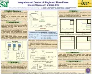
Functionality Diagram • Blue (boxes, arrows) means logical stages and system direction flow • Light red accent boxes describe physical components (interact with some stages) • Red(boxes, arrows) denote critical system errors status • Green (boxes, arrows) define successful checking of some components correct availability
UI Interface Report • User friendly • Windows Presentation foundation platform (WPF) • Data transmitted through UART • Powered by SQL Server Compact database engine • Live data monitor, system current status, current weather, three analytical reports and system settings.
Charging Efficiency Report • Percentage of IRPS being at specific mode of charging • Filtered by date range option • Query software database to pull real time data • Clear indicator from best mode to operate at IRPS location
Diversion Charge Controller • To protect the battery from overcharging and over discharging • Monitor the battery voltage • Divert the power to the dump load • Charging window: 11.9-14.9V • Wind generator: Dump mode • Soar panel: Open circuit mode
Battery Bank 7.15 in • Universal Power Group (UPG) UB12180 D5745 Sealed AGM-type Lead-Acid Battery • Nominal voltage: 12 volts • Periodically charge and discharge • Should be charged under constant voltage. • Durable 6.60 in 3.06 in
Testing- Voltage Monitoring • Wind Turbine
Testing- Integrated Charge Mode • Integrated Solar
Testing- Integrated Charge Mode • Integrated Wind
Lessons Learned • What works in simulation does not mean it works in the real world • Should always think few steps further • Backup is always needed
References • M. Chen, "The Integrated Operation of Renewable Power System," IEEE Canada Electrical Power Conference, 314-319, 2007.