Download
1 / 1
10 likes | 196 Views
Mode. Read Time (s). Gain (e/adu). Read Noise (e). Typical Read Noise (e). Full Well (ke-). Non-linearity (at Full Well). DRM. 0.5982. 5.3. 10.0. 14.1 (2 reads). 180. ~1%. MRM. 0.7866. 4.3. 8.6. 4.8 (61reads). 75. ~0.3%.

E N D
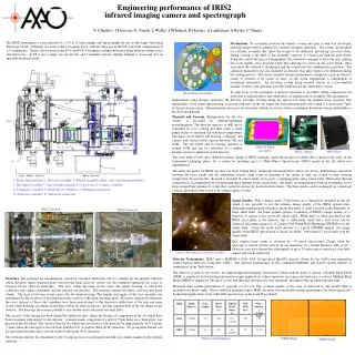
Mode ReadTime (s) Gain(e/adu) Read Noise(e) Typical Read Noise (e) Full Well(ke-) Non-linearity(at Full Well) DRM 0.5982 5.3 10.0 14.1 (2 reads) 180 ~1% MRM 0.7866 4.3 8.6 4.8 (61reads) 75 ~0.3% 1. Main structural plate 2. Detector assembly 3. Wheels assembly (filter, cold stop and grism wheels) 4. Slit wheel assembly 5. Anti-vibration mounts 6. Cryocoolers 7. Camera assembly 8. Collimator assembly 9. Field lens 10. Window 11. Multilayer insulation 12. Detector controller 13. Electrical connectors IRIS2 Internal IRIS2 External V. Churilov, J Dawson, G. Smith, L Waller, J Whittard, R Haynes, A Lankshear, S Ryder, C Tinney The IRIS2 instrument is a near infrared (λ = 0.9 to 2.5 μm) imager and spectrograph for use on the Anglo Australian Telescope (AAT). Primarily it is used at the Cassegrain focus, with the telescope in the F/8 wide field configuration (8 x 8 arcminutes). It may also be used in the F/15 and F/36 Cassegrain configurations providing different image scales and field sizes. At F8 it has a single 1arcsecond slit, and 3 multislit stations offering multiple 1 arcsecond slits on specially produced masks. Mechanisms. To accurately position the wheels a worm and gear system was developed, utilising stepper motors adapted for vacuum cryogenic operation. The worms are mounted on a flexure assembly that allow the worms to be deflected, preventing excessive loads, during cooling as the shell of the assembly contracts at a faster rate than the gear wheel. Solenoids control the gear set engagement, the solenoid is engaged to drive the gear, pulling the worm slightly away from the wheel thus allowing it to drive on one active flank. Once at position the solenoid is disengaged and the worm locks the combination in position. The solenoids themselves are also mounted on flexures that allow them to be deflected during the cooling process. The worm assembly flexure mechanism is designed to give an effective centre of rotation at its centre of mass, so the worm engagement is independent of instrument orientation. An encoding system using infrared sensors in a non-standard manner, to allow cold operation, provides feedback for the wheel drive system. To trim focus of the instrument a detector translator is provided, which compensates for drifts due to thermal effects and small errors in manufacture or assembly. This mechanism, Engineering performance of IRIS2 infrared imaging camera and spectrograph Main Wheel Assembly implemented using flexures, translates the detector assembly 0.4mm along the optical axis from the nominal focus position. The repeatability of the wheel repositioning, as proven with tests on the slit wheel, has been demonstrated to be within 0.1 arcseconds (7μm) of the previous position. All mechanisms have proven extremely reliable in service with no instrument downtimes being attributable to the drive mechanisms. Thermal and Vacuum. Refrigeration for the two vessels is provided by Gifford-McMahon cryorefrigerator. The detector operates at 66K and is controlled by over cooling and then using a strain gauge heater to maintain the stabilized temperature. The main vessel wheels and housing, collimator and camera, and various baffles operate between 75K and 100K. The slit wheel and its housing operates at around 110K and can be controlled via a similar heating system as employed on the detector Multislit Mask Assembly Mask Cutting MOS Mask The wide field-of-view and collimator-camera design of IRIS2 naturally raised the prospect of multi-object spectroscopy early in the instrument’s planning phase. So a system for installing up to 3 Multi-Object Spectroscopy (MOS) masks in the slit wheel was implemented. The multi-slit masks for IRIS2 are laser cut from 100m thick, chemically-blackened brass sheet (see above). Differential contraction between the brass masks and the aluminium wheels could result in buckling of the masks as they are cooled to their working temperature. To prevent this, the mask is mounted in a brass frame of two parts: a clamping plate; and a carrier plate. Differential thermal contraction is accommodated by incorporating three flexures in the carrier plate. All masks are manufactured with an asymmetric set of holes around their perimeters so that they cannot be incorrectly loaded in their frames. The three masks can be exchanged on a timescale of days, allowing for the vessel to be warmed and re-cooled. Image Quality. With a matrix mask (75μm holes on a 3mm pitch) installed in the slit wheel it was possible to test the intrinsic image quality of the IRIS2 optical train. Although manufacturing tolerances meant that there is some variation in the diameters of these mask holes, the mask permits precise evaluation of IRIS2's image quality as a function of camera focus across the whole field. While there is some curvature of the IRIS2 focal plane at the detector, this is sufficiently small that a best focus can be achieved delivering images of <1.2 pixels Full Width Half Maximum (FWHM) over the whole field. Given the mask itself delivers 1-1.1 pixel (FWHM) images, the image quality of the IRIS2 optical train is clearly excellent - better than 0.3 arcseconds over the whole field. Best camera focus seems to decrease by ~35 motor micro-steps (22μm)when the telescope is moved off the vertical (in any direction) by a Zenith Distance (ZD) of 41°. However tests have shown that adjustments of up to 75 motor micro steps have very little impact and can be neglected. Image of Rho Ophiuchus Obtained with IRIS2 Detector Performance. IRIS2 uses a HAWAII-1 10241024 18.5m pixel HgCdTe detector, driven by the AAO’s new generation AAO2 Optical Detector Controllers (ODC). The detector performance of the combined HAWAII1 and AAO2 system delivers is summarized in the Table below. The detector is used in two modes: for high background imaging observations where readout speed is critical, a Double Read Mode (DRM) is employed. In low-background spectroscopic applications, where exposures are longer and read noise is critical, Multiple Read Mode (MRM) is employed. The array is reset and then non-destructively read repeatedly throughout the specified exposure time Measured dark current performance is typically 0.1-0.2 e-/s. The cosmetic quality of the array as delivered by the AAO2 ODC is excellent (see below right). These combined parameters give IRIS2 excellent read-noise/dark current performance for observing in low-background applications such as R=2400 spectroscopy in the J and H passbands. Structure. The potential for misalignment caused by structural deflections led to a scheme for the internal structure where the plate (main structural plate) between the main and fore vessels was the common foundation for a pair of hexapod trusses (Stewart platforms). The truss within the main vessel carries the wheels housing, to which the collimator and camera assemblies and the detector are attached. This housing contains the filter, cold stop and grism wheels. The truss in the fore vessel carries the slit wheel housing. The lengths and angles of the truss members are determined by the locations of the wheel housings relative to the main structural plate. However, inspired by Serrurier, the cross sections of these truss members have been proportioned so the transverse deflections of the fore and main vessel wheel housings are identical and there will be no relative motion, and thus minimal drift of the slit image on the detector. The housings also remain parallel to one another and to the main structural plate. The success of this design has been ratified by deflection tests, where the flexure of components in the slit wheel have been examined with respect to the detector. A matrix mask, comprised of a grid of 75μm holes on a 3mm pitch, was placed in the slit wheel. This showed that the slit wheel moved relative to the detector by approximately by 0.5 pixels (~9μm) when the telescope is moved from Zenith to 60° in an East-West (E-W) direction. No perceptible flexure can be seen when the telescope is slewed in the North-South (N-S) direction. The external structure for attachment to the Cassegrain focus was designed and built in a similar manner to the internal structure. Detector Performance DRM Mode MRM Mode