Download
1 / 38
380 likes | 395 Views
This presentation discusses the collaboration between KEK, LAL, LAPP, and LLR colleagues on the ATF2 project at KEK and the ILC Machine Detector Interface. It covers the goals, R&D programs, and current status of the project.

E N D
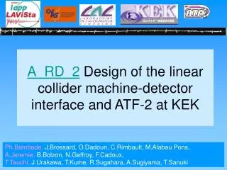
A_RD_2Collaboration on the ATF2 project at KEK and on the ILC Machine Detector Interface Benoit BOLZON (LAPP) for KEK, LAL, LAPP & LLR colleagues FJPPL’10, LAPP, 15-17 June 2010
ATF2 (Accelerator Test Facility 2) KEK (High Energy Accelerator Research Organization) Tsukuba, Japan
ATF International Collaboration CERN DESY IN2P3 LAL LAPP LLR John Adams Inst. Oxford Univ. Royal Holloway Univ. Cockcroft Inst. STFC, Daresbury Univ. of Manchester Univ. of Liverpool University College London INFN, Frascati IFIC-CSIC/UV Tomsk Polytechnic Univ. KEK Waseda U. Nagoya U. Tokyo U. Kyoto U. Tohoku Univ. Hiroshima U. IHEP PAL KNU RRCAT SLAC LBNL FNAL Cornell Univ. LLNL BNL Notre Dome Univ. Oversea collaborators visited for R&D at ATF ~25 Institutes, ~70 peoples, ~2000 people-days per year +KEK and Japanese Universities
ATF2: scaled version of ILC & CLIC final focus • Test of a new local chromaticity correction scheme • Development of beam tuning procedure Goal A : nanometer beam size - obtain y ~ 35 nm at focal point - reliably over long time Goal B : trajectory stabilization - 1-2 nm at focal point - intra-train feedback (ILC-like trains) • Development of ILC instrumentation (BPM, BSM, OTR, LW, WS,…) • Various R&D programs with international collaborators • Education of young researchers in contact with experts (many thesis achieved)
Present ATF2 status: commissioning • Final Focus System (FFS) • Scale test of ILC FFS optics • Extraction Line (EXT) • Extract beam from DR • Correct for coupling and dispersion errors • Correctly match beam into FFS • Before January 10: βx=8cm; βy=1cm • (Nominal σy=800nm) • In January 10: test of different optics with lower β-functions and check the background Background stayed sufficiently low for the Beam Size Monitor (BSM) with the optics: βx=4cm; βy=1mm optics chosen (Nominal σy=105nm with sextupoles knobs)
Present ATF2 status First continuous week of ATF2 beam tuning at the end of May 10 • Goal: Merging of full Extraction and Final Focus System tuning procedures developed to bring down IP spot size to 100nm • DR tuning • COD, dispersion, coupling, E match … • EXT + FFS steering, setup • Cav. BPM cal, BBA, steering, background reduction • EXT tuning • Dispersion, coupling correction • Matching into FFS • FFS tuning • Check match conditions at IP • “Coarse” IP matching (beta, alpha, dispersion) • e.g. “Irwin Knobs”, MAD/SAD rematching • Fine tuning of IP aberrations with “multiknobs” and IPBSM “Shintake Monitor”. • Waist, dispersion, coupling, sensitive second-order terms. • Sextupole mover-based multiknobs, FD roll scans, EXT skew-quad scans… BBA Dispersion correction Twiss parameters Dispersion correction
Present ATF2 status First continuous week of ATF2 beam tuning at the end of May 10 • Fine tuning of IP aberrations with “multiknobs” and the IP BSM (for σy<1um) IP BSM • Iterative use of various knobs to bring down IP spot size by scanning with IPBSM • Sextupole multiknobs and 30 degree mode of BSM could be tested for the first time Tuning from initial setup of 850nm down to 300nm during 16 hours • Beam size cross-checked on BSM 8-degree & 30-degree mode • Trouble reducing σy past 300nm in 30-degree mode as do not have the resolution to scan higher beam sizes
ATF short term plan: October 2010- June 2011 • Achievement of a vertical beam size of 37nm for December 2010 • Two continuous weeks of ATF2 beam tuning are requested in the fall of 2010 • Precision analyses of betatron oscillation propagation to reconstruct R and T matrices • Check sextupole correctness, any abnormal higher order fields and transfer matrices between sextupoles • Final doublet mounting & alignment precision issue of field quality ? • re-measure + assessment… • Background simulation & measurement to assess lower β* feasibility • Encourage collaborators to develop and automate their beam tuning tasks in the control system, e.g. via the Flight Simulator or V-system • Systematically monitor IP size versus beam fluctuations & explicit changes • Studies of fast kicker for ILC should be finished
FJPPL contribution to ATF2 • LAPP: Stabilization study & Mechanical support for the Super Conducting Magnet, beam tuning & software tools A. Jeremie, B. Bolzon (ANR Post-doc) • LLR: Background evaluation (algorithm, GEANT 4) Instrumentation & Experimentation for validation M. Verderi, H. Guler • LAL: Beam tuning & control, software tools, computing, Commissioning strategy & organization P. Bambade, Y. Rénier, C. Rimbault, S. Bai (IHEP) • KEK: BSM, beam tuning strategy, Infrastructure, host & direct partner in all activities T. Tauchi, T. Kume, S. Kuroda, T. Okugi, R. Sugahara, J. Urakawa, H. Yamaoka Collaborations: UK, SLAC, CERN, IHEP, Valencia N.B.: we've had annual dedicated meetings, the last one Monday 14/6 on the ATF2 future and upgrade path
LAPP : Beam tuning & Software tools
Beam waist measurements with QD0FF • Goal: Measurements of the Twiss parameters in order to check the matching of the beam through to the IP • Principle: Scan of the strength of QD0FF around its nominal value and measurement of the corresponding beam size at the IP or Post-IP • Measurements done • First stage of the ATF2 beam tuning: vertical beam size>3um at IP • Beam size measured with wire scanner and laser wire at IP/PIP • Some measurements before α and β rematch (representative results) • βx, βy mismatch of a factor 2 at maximum • Can be easily corrected • εx at reasonable values • QD0FF strength far from its nominal value at the experimental waist • Under investigation (already found that it can not be due to errors on the energy) • QD0FF strenght different in X and Y at the experimental waist: multikobs needed B. Bolzon…
Beam waist measurements with QD0FF 2. Software implemented in the control room to automate these measurements • Implemented via the “Flight Simulator” interface, application allowing international collaborators to develop tuning software even remotely • Control of the wire scanners at IP/PIP, read of the detector data and twiss parameter analysis: successfully tested! • Integration of multiknobs to correct αx, αy and Dx under development • Future prospects: find the beam automatically with WS thanks to BPM-based modelling currently very accurate • My personal experience: implementation very easy via the FS • Few automated tasks currently implemented in the FS • People are welcome to implement their algorithms and can require beam time to test them with very good beam conditions!! B. Bolzon…
Multiknobs for the IP/Post-IP • Correct independently the horizontal and vertical waist (αx and αy) and the horizontal dispersion (Dx) generated in the FFS • Multiknobs found to be well orthogonal and • linear (simulation): QD0FF, QF9BFF, QF1FF High Dx Low Dx High β-functions QF9B QD0/QF1 • αy knob successfully tested for beam waist measurement during the continuous week • Dx stayed within mm range • No increase of σx at each scan point (15um, close to the nominal value) Experimental Simulation Minimum σy=3.5um for αy=18 βy well matched B. Bolzon…
LLR activity :Background modeling @ ATF2 M. Verderi, H. Guler
Motivations and approach • ATF2 offers opportunities for background studies of: • The Final Focus region • Mind this is a scale down of the ILC/CLIC FF • Mainly EM background from beam halo • Particles backscattered from beam dump • Mainly neutrons • Interest for ILC/CLIC are neutrons backscattered from dump but also neutrons produced in dense materials near IP by EM background • That, beyond ATF2 interest itself • Modeling approach relies on: • Measurements • Specific • With dedicated apparatus made @ LLR • General to ATF2 • Requires synchronizing dedicated measurements with ATF2 ones • Simulation • With Geant4 and BDSIM/Geant4, tools that are used by ILC/CLIC • With the challenge of boosting the simulation by order of magnitudes to get workable background statistics ! M. Verderi, H. Guler
Hardware and acquisition Detectors (examplewithusing a box) • Made a set of 8 simple detectors = {scintillator + photomultiplier} • That can be used alone • Or assembled in boxes to form « mini-calorimeters » with longitudinal segmentation (with W insertion if needed) • Scintillator = plastic or pure CsI • Fast : allows TOF • Distinguish background sources • Separate (prompt) EM and (delayed) neutron backgrounds • Different response to neutrons: • Plastic sensitive to fast neutrons • Intermediate neutrons for CsI • Tests done with cosmics, e+’s (DESY), neutrons (Am/Be source CEA) in 2009 • Have been transported to KEK end of 2009 Acquisition HT CAEN Rack PC NEC Agilent 1GHz sampling modules (Philip’skindness) Synchronizationwith ATF2 : ATF2 data readfrom LLR acquisition M. Verderi, H. Guler
Boosting the simulation : event biasing technique(s) « Straightforward » beam dump simulation : => 10k simulated e- leads to O(1) hit in detector (in red here) outside the beam dump! Shintake detector Beam dump • Straigthforward simulation is inefficient at producing background events : they are « rare events » eg: • Electrons that departs from the ~1010 electrons in core beam • Particles that scatter back from beam dump • Particles (neutron) that fully traverse the beam dump • … • « Biasing techniques » allow to obtain workable statistics, by artificially enhancing rare event occurrence: • Example : « splitting » technique • There exist others neutron Picture with 50 incident 1.3 GeV e- Biased simulation, with « splitting » technique : particles reaching blue boundaries are cloned (if moving to outside) or randomly killed (if moving to inside): => Splitting conterbalances outgoing flux attenuation. Killing (by ½ here) × splitting (by 2 here) Slices (blue) on which « splitting » occurs M. Verderi, H. Guler
Boosting the simulation : event biasing technique(s) « Straightforward » beam dump simulation : 10k simulated e- leads to O(1) hit in detector (in red here) outside the beam dump! Shintake detector Beam dump • Straigthforward simulation is inefficient at producing background events : they are « rare events » eg: • Electrons that departs from the ~1010 electrons in core beam • Particles that scatter back from beam dump • Particles (neutron) that fully traverse the beam dump • … • « Biasing techniques » allow to obtain workable statistics, by artificially enhancing rare event occurrence: • Example : « splitting » technique • There exist others neutron Picture with 50 incident 1.3 GeV e- Biased simulation, with « splitting » technique : efficiency improved by a factor ~1000 (even in this un-optimized version) ! Of course : a technique not limited to ATF2 ! Picture with 50 incident 1.3 GeV e- M. Verderi, H. Guler
First DATA/MC « comparison » • Recent (May 2010) measurements, at beam dump, together with corresponding simulation with biasing • Still many work to do… • But above plot demonstrates that hardware and software have both reached a workable state. • First results to come in the next weeks ! (-) Energy deposit as function of time in « Plastic - CsI - Plastic » scintillators near beam dump. 100K incident e- in beam dump MC CsI Plastic Plastic Average of 100 photomultiplier signals for « Plastic - CsI - Plastic » scintillators near beam dump. DATA Neutron delayed signal HIGHLY PRELIMINARY !!!! EM prompt peak M. Verderi, H. Guler
LAL: Beam tuning & control, software tools, computing Commissioning strategy & organization
Simulation of multiknobs correction (βx,y=8,1cm) • Simulation of 1mrad rotation and 1% strength errors at all quadruples in ATF2 line • Random relative field errors in all ATF2 quadrupoles, with RMS of 0.01 • Correction of 100 seeds (minimum vertical beam size scan) at the Post-IP using : Waist corrected with FD Dispersion correction with skew quads Coupling correction with skew quads Coupling correction with skew quads y demagnification Tail due to FD errors: more iterations needed • Vertical beam size close to the nominal one with only one iteration: procedure efficient, easy and fast • Shift the waist from the Post-IP to the IP: vertical beam size preserved • Makes tuning at the post-IP feasible to prepare the beam for the BSM • Advantage: 5um carbon wire at PIP with 1um resolution S. Bai, B. Bolzon…
Coupling measurements in ATF2 EXT - 1 • Projected beam size measurements at x, 80o, y and 100oat 4 wire-scanner positions varying the strenght of the QK1X skew quad. • Coupling reconstruction using: • Verification of the coherence between 80o and 100o • measurements • Search for an automatisable method to reconstruct • the beam matrix at QK1X position: • The more reliable method consists of: a. Constrain 6 elements with s33 fits b. Constrain 3 elements with s13 fits c. Constrain the last one with s11 fits C. Rimbault
Coupling measurements in ATF2 EXT - 2 at QK1X Comparison between measurements and beam matrix reconstruction result propagation s33 s13 - Physical results but large error bars. - Large number of data sets is required to minimise statistical errors. C. Rimbault
Transfer matrix check • Introduce a kick with a corrector or moving a quad. • Measure trajectory variation • Compare with predictions from model • Useful to check instrumentation coordinate system, BPM calibration … • Automatized and quick (1min / corrector) Y. Renier
Trajectory correction • ___ before correction ___ after correction • 5 corrections iterations in extraction line • Launch in final focus system • 5 corrections iterations in final focus system • Performances : Y. Renier
Dispersion measurements from fluctuations • Dispersion measured by varying energy • Sub-micron cavity BPM resolution • Reconstruction of energy fluctuations • At each BPM, measurement of the dispersion • Fit dispersion on all BPMs • Dispersion measuredfrom fluctuations • Allow parasitic dispersion measurements Y. Renier
ATF2 @ IPAC’10 (FJPPL contribution) • G. White et al., Operational Experiences Tuning the ATF2 Final Focus Optics Towards Obtaining a 37nm Electron Beam IP Spot Size • B. Parker et al., A Superconducting Magnet Upgrade of the ATF2 Final Focus • B. Bolzon et al., Linear Collider Test Facility: Twiss Parameter Analysis at the IP/Post-IP location of the ATF2 beam line • S. Bai et al., Simulation of Multiknobs Correction at ATF2 • E. Marin et al., Scenarios for the ATF2 Ultra-Low Betas Proposal • C. Rimbault et al., Coupling Measurements in ATF2 Extraction Line • Y. Kamiya et al., Development of Shintake Beam Size Monitor for ATF2 • Y. Yamaguchi et al., Evaluation of Expected Performance of Shintake Beam Size Monitor for ATF2 • Y. Kim et al., Development of Electronics for the ATF2 Interaction Point Region Beam Position Monitor • S. Boogert et al., Cavity Beam Position Monitor System for ATF2 • M. Hildreth et al., The Straightness Monitor System at ATF2 • D. Okamoto et al., First Beam Test of the Tilt Monitor in the ATF2 Beam Line • Y. Iwashita et al., Beam Test Plan of Permanent Magnet Quadrupole Lens at ATF2 • T. Kume et al., Straightness Alignment of Linac by Detecting Slope Angle • T. Naito et al., Multi-bunch Beam Extraction using Strip-line Kicker at KEK-ATF • A. S. Aryshev et al., Sub-micrometer Resolution Transverse Electron Beam Size Measurement System based on Optical Transition Radiation
Theses and publications @ ATF2 FJPPL contribution • After the 4 thesis, good job found in the same domain (in particularly 3 people were recruited by CERN)
ILC Machine Detector Interface: ILD vibration studies H. Yamaoka
QD0(700kg) BeamCAL(100kg) LHCAL(3000kg) LumiCAL(250kg) ECAL(420kg) Vibration properties of the ILD QD0 support system has been studied. To improve vibration behavior; We need to solve these issues. 3. Correct? Check consistency 2. Calculations - Static - Modal - P.S.D. 1. Design of stiff support structure QD0 support system 4. Vibration data - CERN - KEK - Coherency? 5. Realistic data Criteria Allowable Amplitude:< 50nm(V) (Above 5Hz) < 300nm(H) H. Yamaoka
Calculation P.S.D. (Power Spectrum Density) analysis has been carried out with real measurement data. Respond amplitude at each position is estimated. Thicker: 200t400t 1.3mm(inner) 31Hz(1st mode) Additional ribs 3.8mm(Outer) 8.6Hz(1st mode) 54nm>5Hz Inner cylinder: Self-weight + 1tonnes(QD0) Fixed Outer cylinder: 4tonnes 0.6nm>5Hz P.S.D. Integ. Amp. H. Yamaoka
Measure vibrations on the Belle ? ? ? ? ? Vibration measurements at the Belle/KEKB/CMS/ND280 Study items - Vibrations on each place - Coherency between both sides - etc Result Measure vibrations on KEKB Result ? ? Further measurements/plan; - BELLE solenoidal field with immune to magnetic fields(SP500). - Vibration when beam is circulating with SP500. ・Improving the magnet/BELLE/etc support structure. ・Collision orbital FB. No active cancellation system is considered at this point. ? ? Measure vibrations on CMS H. Yamaoka
Various contributions of the French team to ATF2 and strong collaboration with the Japanese team and the international collaborators • Background instrumentation and several beam tuning tools developed and tested • Lots of R&D project up to 2015 (ultra-low β, SuperConducting FD…) • First continuous week of ATF2 beam tuning: merging of all the tuning tools and instrumentation developed by international collaborators to decrease the beam size • Beam size of 300nm achieved: very successful for a first test!! • Learned a lot about what to do afterwards • Next step: nominal optics to achieve beam size of 37nm at the end of this year • ILD vibration studies • Vibration measurements and simulations of the ILD QDO support done • Vertical vibration tolerances (50nm) respected with a high ground motion • Vibration measurements at the Belle/KEKB/CMS/ND280 performed • Improvement of the magnet/BELLE/etc support structure is needed • FJPPL: Encouragement of international collaborations by providing them a frame • Several young doctorates and post-docs could been trained and have acquired competences in the contact of research teams working at the state of the art in the domain of accelerators