Download
1 / 7
70 likes | 194 Views
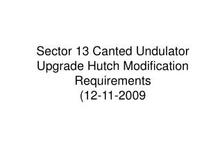
Sector 13 Canted Undulator Upgrade Hutch Modification Requirements (12-11-2009. Wall penetration modification needed to accommodate the two guillotines, one for the shielded beam pipe the other for the 13-ID-C1 mono beam pipe.

E N D
Sector 13 Canted Undulator Upgrade Hutch Modification Requirements(12-11-2009
Wall penetration modification needed to accommodate the two guillotines, one for the shielded beam pipe the other for the 13-ID-C1 mono beam pipe Wall penetration and guillotine needed to accommodate the shielded beam pipe to 13-ID-C2 New wall labyrinth IDC2 movable back stop Horizontal Large KB mirror. Moved from IDB to front of IDC2 Center line of 13-ID-C2 line 305 mm Center line of 13-ID Microprobe Table Shielded Beam Pipe Diffractometer moved downstream Center line of 13-ID-C1 New Wall. This is classified as white hutch front wall. Shorten existing crane for operation in C2. Add new crane for operation in C1. New wall labyrinth New pneumatic white beam door shown 48.5” wide opening. PSS box moved from hutch wall a false wall that allows sliding doors to pass behind
Notes • At least four more labyrinths should be included (2 wall and 2 roof). • Utilities: • PSS: • A complete set of components (search buttons etc.) will be required for C1. • Search button, flashing light and speaker in the front of C needs to be moved to C2. • Crane: • Shorten existing crane in C2. • Add new crane to C1.
Phase Plan • In order to minimize the impact on the existing user program on the ID line we would like the hutch modification to occur in three phases with the work to be done during three shutdowns. After each phase the sector should be able to be brought back on line. We plan on being dark during the 2011-3 run to accommodate front end installation. • Two major changes are needed to complete the hutch modification; 1) PSS components need to be added or moved and 2) hutch shielding modification. The hutch modifications will most likely require that three outboard panels be removed and replace with three new (or modified existing) panels, two that will incorporate a sliding door and one with a triple joint providing an attachment for the new wall. To allow access to the these hutch panels both the electrical and PSS components need to be moved. • Phase One (maintenance period 1 January 2010)(see pages below for more details) • In phase one the outside and inside of the outboard walls need to be cleared of components so that during the next phase the wall panels can be modified. This involves moving the PSS box, separating conduit for AC power and PSS and moving an electrical panel. The inboard wall requires the separation of the electrical conduit shortening water and compress air so that it is only available in C2 and moving electrical outlet strips. It is important to note that after this phase the beamline should operate as before therefore modifications to the PSS will only be to make room for future wall panel changes but not modify the PSS logic, hardware or wiring. We will be operating the IDC hutch in the same way we did prior to the shutdown. During this phase the overhead crane track will be shortened as well. • Phase Two (maintenance period 2 May 2010) • With utilities and PSS out of the way the wall panels can be removed and the door and triple junction panel installed. The goal of this phase is to remove and then replace the hutch shielding during the shutdown so it is not required to install the interior wall. The new exterior door will be chained or wielded closed until the final phase is completed where the PSS is modified to operate with the new configuration. • Phase Three (maintenance period 4 January 2011) • With the new exterior walls and door installed during phase two the remaining work to be performed involves installing the PSS connections and PLC update, installing the interior wall and modification of the front wall of IDC to allow for both canted beams to enter and a clean interface for the IDC1 (mono / pink) and IDC2 (GBS) shutters and guillotine. During this phase the new PSS configuration will be installed and tested to allow 13IDC1 and 13IDC2 to be searched but the shutter logic will not be installed. Panels needing replacement or modification
Phase One Clear outside panels Remove PSS components and light switch from this wall. Mount on free standing frame that will allow the doors to slide behind it.
Phase One Clear inside panels outboard Move electrical panel to roof. Separate electrical and PSS conduit routing it out a labyrinth located in the C2 hutch and back in a labyrinth in the C1 hutch. Note there is no change in the PSS logic at this time we are simply moving conduit to make room for wall removal and wall installation work for the next shut down.
Phase One Shorten water and compress air to that it is only available in C2 Separate electrical conduit routing it out a labyrinth located in the C2 hutch and back in a labyrinth in the C1 hutch. Clear inside panels inboard Move to next downstream panel.