Download
1 / 23
570 likes | 2.16k Views
Hydraulic Lines and Fittings. Lecture 8. Purpose of Lines. All hydraulic lines are designed to transmit fluid from one place to another without leaking Lines are built to withstand pressure, vacuum, and the hydraulic fluids used in the system There are two different types: Flexible and Steel

E N D
Hydraulic Lines and Fittings Lecture 8
Purpose of Lines • All hydraulic lines are designed to transmit fluid from one place to another without leaking • Lines are built to withstand pressure, vacuum, and the hydraulic fluids used in the system • There are two different types: Flexible and Steel • All lines have fittings on the end of them to connect to hydraulic devices
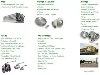
Steel Lines • Steel lines (tubing) is used when there is little vibration, limited space, no movement of the lines, and/or frequent replacement is needed • Steel lines have two common type of connectors: JIC Flare and Flareless Compression
JIC Flare Fitting • Usually has a nut, backup sleeve, and a 37° flare of the line • This type is often used on the outside of cylinders on construction or farm equipment • Can also be used for return lines
Flareless Compression Fitting • A special type of ferrule that replaces the flare • Bites into metal to provide a positive seal that won’t slip • Can be used for return lines • Also used for pressure lines on the frame
Flexible Lines • Many different types and materials used to make flexible lines • All flex lines are measured by the inside diameter of the line • Can use fraction measurement or dash size • All lines rated in working pressure, vacuum, or burst pressure
Line Sizes • Lines can be from 3/16” to 4” in size (Inside Diameter or ID) • Dash size is determined by taking the number and making it the numerator of the fraction 16 • -3 hose size is 3/16” (3/16) • -12 hose size is 12/16” or ¾” (12/16) • Largest is –64 size (4”)
Hose Materials • Most hoses have an outer covering, a cloth or wire braid, and an inner material to prevent leakage • Can be damaged by high temperatures • Neoprene or Buna-N used in most hydraulic hoses • Wire braids added to handle high pressures
Hose Maintenance - Replacement • Leaks at fitting or in hose. (Leaking fluid is a fire hazard.) • Damaged, cut, or abraded cover. (Any reinforcement exposed.) • Kinked, crushed, flattened, or twisted hose. • Hard, stiff, heat cracked, or charred hose.
Hose Maintenance - Replacement • Blistered, soft, degraded, or loose cover. • Cracked, damaged, or badly corroded fittings. • Fitting slippage on hose.
Hose Routing • Make sure to install hoses so that they are as close as possible to the component • This keeps the line from being pulled off • Keep a little slack in all lines to allow movement
Hose Routing • Make sure the line flexes in and out rather than up and down • Minimize movement if possible
Hydraulic Fittings • Several types of fittings used on hydraulic components • NPTF (National Pipe Tapered - Fuel) • JIC (37°) • O-Ring Boss • O-Ring Flange • Flat Faced O-Ring (Forseal)
NPTF Fittings • The most commonly used on older equipment • Seals by a tapered thread • The farther you turn it, the better it seals • Standard pipe thread can leak without the use of pipe sealant
JIC Fittings • The next most common fitting used • Seals by seating an angled flared area against another angled area • Can leak if the seating area is scratched • Hose end can be easily disassembled and repositioned
O-Ring Boss • Uses an O-Ring to seal the fitting • Often has a jam nut that is used to compress the o-ring • Permits turning an angled fitting to a desired position without leaking
O-Ring Flange Fittings • Primarily used on hose ends • Has a round flat surface that uses an o-ring to seal it against the component • Is compressed by a separate backup flange that usually has 4 bolts • Can leak if the flange is bent or the surface is scratched
Flat Faced O-Ring Fittings • Also called Forseal fittings • Similar to JIC except the seating area is flat and the fitting has an o-ring in it • Can leak if the face is deeply scratched or o-ring is bad • Newest type used on hydraulic equipment
Fitting Installation - NPTF • Inspect port components to ensure that male and female threads are free of nicks, burrs, dirt, etc. • Apply sealant/lubricant to male pipe threads. With any sealant, the first few threads should be left uncovered to avoid system contamination. If Teflon tape is used, it should be wrapped 1-1/2 turns in a clockwise direction when viewed from the end.
Fitting Installation - NPTF • Screw Fitting into female pipe port to finger tight position. • Wrench tighten fitting to the appropriate Turns From Finger Tight in the next chart, making sure the tube end of the shaped fitting is aligned to receive incoming tube or hose assembly.