
§8—3 V带传动的设计计算
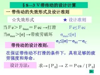
§8—3 V带传动的设计计算. ☆ 失效形式 ★ 设计准则. 一 带传动的失效形式及设计准则. 当F e >F fmax =F ec → 打滑 F e≤ F ec. 当 σ max > [σ] → 带疲劳破坏 σ max ≤[σ] σ 1 ≤[σ] - σ b1 - σ C. 带传动的设计准则 :. 在保证带传动不打滑的条件下,具有足够的疲劳强度和寿命 。. 设计方法:. 求→ [ P 0 ] → Z=P ca / [ P 0 ]. 二 单根V带的基本额定功率P 0.

§8—3 V带传动的设计计算
E N D
Presentation Transcript
§8—3 V带传动的设计计算 ☆失效形式 ★ 设计准则 一 带传动的失效形式及设计准则 当Fe>Ffmax=Fec →打滑 Fe≤Fec • 当σmax>[σ] →带疲劳破坏 σmax≤[σ] • σ1≤[σ]-σb1-σC • 带传动的设计准则: • 在保证带传动不打滑的条件下,具有足够的疲劳强度和寿命。 • 设计方法: • 求→ [P0] → Z=Pca/[P0]
二 单根V带的基本额定功率P0 P0=FecV/1000 →单根带可传递最大功率 Fec≤F1(1-1/efva) →不打滑 (一).P0计算式 F1=σ1A σ1≤[σ]-σb1-σc→足够的疲劳强度 ∴单根V带可传递功率P0: P0=([σ]-σb1-σc)A(1-1/efva )V/1000kw (二). 单根V带的基本额定功率P0(特定条件) 1.P0:按dd1、n1、型号→查表(8-5a) p.148 2. 特定条件: ①载荷平稳 ②包角α1=π(i=1); ③特定长度
3. 非特定条件下的修正系数 ①工作系数KA→ 非平稳载荷KA> 1表(8-6) ②包角系数Kα: 表(8-8) 当α1<π →承载力↓→Kα< 1→α1 ↓→Kα↓ ③长度系数KL : 表(8-2) 当L>特定条件→绕转次数N ↓→传动功率↑ →KL >1 当L<特定条件→绕转次数N ↑→传动功率↓ →KL< 1 表(8-5b)P.149 当i>1→dd2↑→σb2 ↓→承载力↑→传动功率↑ → △P0 >0 4. 单根V带功率增量△P0
单根带的许用功率:[P0]= (P0+△P0) KαKL 总功率 :Pca = KA P 带的根数: Z= Pca / [P0] 三 单根V带的许用功率[P0] 四 V带传动的设计计算 1. 设计方法: 已知:P、n、i、工作条件选择:带的型号、dd、Ld、 a=(0.7~2)(dd1+dd2)求: 1. Z=Pca/[P0] 2. F (压轴力) 验算:V , α 1≥120° 2 . V带传动的设计步骤
带根数 Z= Pca / [P0] 计算 Pca = KA P ——由Pca和n1查表 选择带的型号 选择dd ——套基准直径 验算V 1≤15m/s ——套基准长度 计算Ld、 a 验算 α 1≥120° ——取整数 计算压轴力F 设计带轮 ——画零件工作图