Efficient Flying Wing Design for Radio-Controlled Model Aircraft
190 likes | 239 Views
This conceptual design presentation covers wing and engine selection, takeoff and landing distances, passive lift enhancement, and static stability for a high-performance flying wing model aircraft. Key aspects include wing loading optimization and propulsion system specifications. The presentation concludes with stability analysis and performance conclusions.

Efficient Flying Wing Design for Radio-Controlled Model Aircraft
E N D
Presentation Transcript
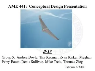
AME 441: Conceptual Design Presentation B-19 Group 5: Andrea Doyle, Tim Kacmar, Ryan Kirker, Meghan Perry-Eaton, Denis Sullivan, Mike Trela, Thomas Zieg February 5, 2004
Overview • Introduction • Main Wing Selection • Engine Selection • Takeoff and Landing Distances • Passive Lift Enhancement • Static Stability • Conclusions
Introduction • Design Drivers • Maximum Level Speed at Constant Altitude • Maximum Climb Rate • Allowable Parameters • Total Planform Area between 400 and 800 in2 • Power Plant Consisting of an Electric Motor • Internal Cargo Bay of Specified Dimensions • Sport Propeller of Specific Pitch and Diameter • Digital Radio Control System (7 Channels)
Why a Flying Wing? • Advantages • Minimum Drag • High Speed • Absence of Horizontal Tail Maximizes Climb Rate Given AC and CG locations • Maximizing Excess Power
Wing Loading • Design Drivers: • Max Level Cruise High Wing Loading • Max Rate of Climb Low Wing Loading • Large aircraft are not a good comparison. • R/C Model Aircraft Wing Loading • Professional Kit Models: 12 oz/ft2. • Conceptual Design: 27 oz/ft2. • Maximize Available Power, Decrease Drag
Overall Wing Design • Taper Ratio, 0.4 – Like Elliptical Planform • Wing Sweep, 20% – Historical Data • Winglets – Decrease Drag, Stability • Dihedral, none • Winglets & Wing Sweep are effective Dihedral • Twist takes away from effective Dihedral
Wing Airfoil Section: EH 3.0/12.0 • Low Moment about A.C. • -0.002 • Thick Section • Structure • Stability • Designed for Flying Wing model Aircrafts
Wing Specifics • Flaps for increase lift at take off and acceleration to cruise. • Dimensions • Wing Area, 600 sq. in. • Compromise between low drag and low CL. • Wing Span, 5.4 ft • A = 7.1, 8.1 with winglets • Root Chord, 1.09 ft & Tip Chord .44 ft • CL @ cruise, .225
Estimated Cruise Velocity Importance • Velocity estimation greatly effects the design of the wing.
Estimated Velocity • Theoretical Estimate: 100 ft/s • Based on a propeller efficiency ranging from .4 to .6 • Conservative Estimate: 80 ft/s • Battery will not be fully charged and other losses will occur.
Wing Twist & Angle of Attack • Twist: For Stability & Control of Aircraft • Minimize Moment @ A.C. • Low Stability Factor, 8% • Longer Wing Span • Good Weight Estimate • Calculated -4° of Twist from Root to Chord • Root Chord, α = 4 ° • Tip Chord, α = 0 ° • Mean Aerodynamic Chord, α = 2.5° • .817 ft long at 1 ft from the root chord.
Propulsion System • Astro 15 Motor • 12” X 8” Pitch Propeller • 9.78 lbs. Static Thrust • 2.16 lbs. Cruise Thrust (2 lbs. of Drag at Cruise)
Take-Off and Landing Analysis • CDO= 0.015 • Aspect Ratio=7.15 • CLG=1 • Take-off Weight= 8lb • =0.1, wet grass • 5 foot obstacle • Wing Loading= 1.687 lb/ft2 • VTD= 43.34 ft/sec • Landing Weight= 7lb • Dropped landing gears • =0.3, wet grass, large surface area interaction with ground
Lift Enhancement • Airfoil Data • EH3.0-12.0 • Cl max = 1.0 • αs 2-D no flaps = 10 degrees • CLmax no flaps = 0.90 • αs 3-D no flaps = 13.129 degrees • Flap Information • Plane • δf = 30 degrees • Sf/Sw = 0.20 • cf/cw = 0.25 • 3-D with flaps • ΔCLmax = 0.0189 • CLmax = 0.9189 • αs 3-D flapped = 11.629 degrees • ΔCD0 = 0.0156
Conclusions • Flying Wing Configuration • Estimated 8 lb Takeoff Weight • Wing Dimensions • Area: 597 in2 • Span: 4.7 ft • Root Chord: 1.08 in Tip Chord: .44 in • Wing Twist: 5° • EH 3.0-12.0 Airfoil • Cl max-1.0 • 3% Camber • 12 % Thickness • Wing Loading • 27 oz/ft2
PowerPlant • Astro Cobalt 15 Electric Motor -Shaft Output Power: 268 W -12 Cell Pack -2.38:1 Gear Ratio -12x8 Propeller • Takeoff and Landing • Takeoff Speed: 48.34 ft/s • Takeoff Distance: 248.57 ft • Landing Distance: 743.12 ft • Flap Information • Plane • Δf = 30 degrees • Sf/Sw = 0.20 • cf/cw = 0.25 • Cruise Speed • 80 ft/s