DOWNHILL
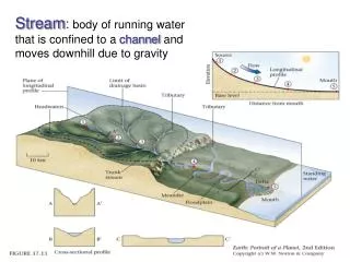
Map of Current Water System (section relevant for EWB-MAP modifications) RED lines – supply lines to tank (uphill by pump) BLUE lines – distributions lines by gravity. DOWNHILL.


DOWNHILL
E N D
Presentation Transcript
Map of Current Water System (section relevant for EWB-MAP modifications)RED lines – supply lines to tank (uphill by pump)BLUE lines – distributions lines by gravity DOWNHILL
Proposed update to Water System (section relevant for EWB-MAP modifications)RED lines – supply lines to tank (uphill by pump)BLUE lines – distributions lines by gravity A F NEW DISTRIBUTION LINE 2a NEW SUPPLY LINE 1 D NEW DISTRIBUTION LINE 2b E DOWNHILL NEW DISTRIBUTION LINE 2c B NEW TANK C
Piping System Layout New Pipelines Waypoints • Supply Line 1 to new tank (A-B-C) • Length = 365 m + tank connection (assume + 10 m) = 375 m • 1 bend, 1 tee, 3 elbow, 2 valves, 1 exit • 17 m elevation rise + tank height • Hill rises to 643 m then valley falls t0 640 m on connecting road (D-B) • ~175 gpmflowrate • Distribution line connection 2a from lower Tramo 3b to lower Tramo 6 (E-F) • 105 m length, elevation change unclear, guess 10 m drop • Distribution connection 2b from upper Tramo 3b to upper Tramo 6 (B-D) • 120 m length, 8 meter drop with low point at 640 m (3 m below D) • Distribution line 2c from new tank to new connections (C-B-E) • 255 m length, 11 meter elevation drop
Proposed update to Water System (section relevant for EWB-MAP modifications)RED lines – supply lines to tank (uphill by pump)BLUE lines – distributions lines by gravity A 20 m DOWNHILL 240 m NEW SUPPLY LINE 1 B NEW TANK C 105 m
Estimate of head losses in supply pipe 1 (smooth PVC) 4” PVC sufficient to keep major and minor losses to >10% of the elevation change
Supply Pipe 1 Pipe Profile(not to scale) C 651 m 655 m B Elevation: 640 m 643 m 105 m 638 m D A 240 m 640 m 20 m Tee connect to 6” pipe Gate Valve 45° Elbow 90° Elbow Gate Valve 90° Elbow 90° Elbow Pipe Exit PIPE FITTINGS NEW TANK
Supply Pipe 1 Trenching • Based on recommendations from EWB Water Resource Guidelines: • 45 cm trench depth • 10 cm bedding (2-12 mm soil) if stones/rocks present in trench • Back-fill with soil that is free of lumps, from stones (>3 cm), and from organic matter • PVC pipe joined in trench and cure for >10 hr prior to pressurizing. Keep joints exposed to check for leaks • For road crossing, bury PVC pipe inside steel or concrete pipe (ID > diameter of PVC joints) and bury at same depth as standard trench 45 cm trench depth 10 cm bedding
Thrust Anchors for Elbows &Tees From Russ Turner, Tetratech
Thrust Anchor Dimensions • Based on • 4” PVC PIPE • 45 cm Trench Depth • Height of Anchor • 22.5 cm • Length of Anchor Backing against undisturbed material: • 90° BEND: L = 83 cm • 45° BEND: L = 41 cm • Tee: L = 41 cm
Supply Pipe 1 Materials List • 4” PVC pipe (Schedule 40) in 6 m lengths – 62 pieces • 4” PVC 45° Elbow – 1 piece • 4” PVC 90° Elbow – 1 piece • Tee connector & Adapter from 6” PVC main to 4” branch line – 1 piece • PVC primer, PVC cement, applicators, and cleanup • Gate/Ball valves (PVC or steel ?) – 2 pieces • 4” Steel Pipe (5 m) – 1 piece • 4” Steel 90° Elbow – 2 pieces • 4” PVC-Steel Pipe Connector – 1 piece • Bed material for trench (2-12 mm), if necessary • Fill material, if necessary • Concrete for Anchoring Piping at Bends • Concrete/Rebar for Valve boxes and lids • Tools for cutting, de-burring, connecting pipe
EPA-NET Simulation for Supply Line 1 Matches Excel Calculations DOWNHILL
Summary of changes in water distribution system CURRENT SYSTEM PROPOSED MODIFICATION Storage Tanque 1: 35,000 gal Tanque 2: 11,000 gal Tanque 3: 25,000 gal New Tank: 28,600 gal Old Pump supplies water to Tanques 1 & 3 at 175 gpm New pump supplies water to new tank at 175 gpm with much lower head Homes serviced by Tanques 154 33 117 New: 280 • Storage • Tanque 1: 35,000 gal • Tanque 2: 11,000 gal • Tanque 3: 25,000 gal • Pump supplies water to Tanques 1 & 3 at 175 gpm, ~3 days per week • Spring supplies water to Tanque 2 (and other tanques) • Homes serviced by Tanques • 291 • 33 • 260 New tank reduces demand of water from Tanques 1&2 (which require high head) by roughly 50%
Current Water Distribution System 260 Homes Served by Tanque 3 291 Homes Served by Tanque 1 33 Homes Served by Tanque 2 DOWNHILL
Proposed Water Distribution System 280 Homes Served by New Tank 117 Homes Served by Tanque 3 33 Homes Served by Tanque 2 154 Homes Served by Tanque 1 DOWNHILL