Collimator Wakefield Issues and Solutions in Particle Accelerators
Understanding and addressing issues related to collimator wakefields in particle accelerators is crucial for successful operation. This project plan outlines the introduction, wake potentials, measurements, and conclusions to minimize wake effects.

Collimator Wakefield Issues and Solutions in Particle Accelerators
E N D
Presentation Transcript
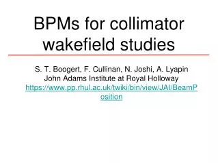
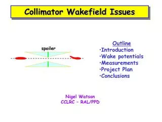
spoiler Collimator Wakefield Issues • Outline • Introduction • Wake potentials • Measurements • Project Plan • Conclusions Nigel Watson CCLRC – RAL/PPD
Introduction • Success of LC requires • High (integrated) luminosity • Acceptable backgrounds • Machine protection • Detectors must be able to turn on and use recorded data • High luminosity • Minimise emittance growth, DR IP • Control relative beam-beam motion at IP • High beam currents Nigel Watson/CCLRC-RAL
spoiler absorber 1mm Spoiler/Absorber • Thin (<1X0) spoilers • spread out beam, multiple Coulomb scattering, dE/dx • Low z bulk, but require durable, low resistivity surface • Damaged surfaces significant effect on WF behaviour • Thick (20-30X0) absorbers, in spoiler shadow SLC, 20mm Au coating on Ti [Decker et al, Linac’96] Nigel Watson/CCLRC-RAL
Collimator Wakefields • Conservative system design, to remove ~ 0.1% of beam • Avoid large amplitude component from entering FF • Mechanical collimators close to beam • Continuously scrape halo (~10kW) • Enlarge spot size of mis-steered beam by Coulomb scattering • Beam excites wake potential in material, acts back on (tail of) bunch: • Transverse loss (“kick”) factor, y’=Ky (near axis) • Position jitter angle jitter • Jitter amplification a la TRC: Ab=Kb; p(1+Ab2)1/2 • Emittance growth De/e A2b Nigel Watson/CCLRC-RAL
Jitter Amplification Comparison De/e A2b • Vertical plane, unacceptablejitter • NB: with tail folding OFF, pessimistic/conservative • Tail folding loosens collimation requirements • Reduces significance of collim. wake fields • Experimental verification? Nigel Watson/CCLRC-RAL
Collimator Wakefields • WF in vertical plane important even in error free machine • Collim at betatron phase of FD most criticaL • Contribute to position jitter of beam at IP • Separate into: to reduce effect use: • Geometric wake smooth tapers • Resistive wall wake high conductivity • Roughness impedance high quality finish • Very difficult to calculate analytically - possible only for simple configurations • Difficult to model, esp. for short bunches (sz~300mm), shallow tapers (a~20mrad), small ½ gaps (b~0.4mm), in reasonable time Nigel Watson/CCLRC-RAL
Data • Recent measurements using dedicated facility at SLAC, study geometric and resistive wakes • Improvements to theory (Stupakov et al) • Geometric wakes for tapered, rectangular collimators • inductive (shallow tapers) • intermediate regime • diffractive (steep tapers) • Resistive wakes (Piwinski et al) • Analytic calculations used in TRC, assuming • is = Cu • no tail folding • near-axis wakes (linear, dipole region) • Near-wall wakes (non-linear) possible machine protection issue Nigel Watson/CCLRC-RAL
SLAC CollWake Expt. 1500mm At 1.19 GeV point in SLAC linac sz ~ 650mm Magnet mover, y range = 1.4mm, precision = 1mm Nigel Watson/CCLRC-RAL
Near wall wakes • Primarily study near axis wakes, dipole mode, ~linear region • Add bump, study near wall region • Non-linear, more important for machine protection Kick angle (mrad) Beam-collim. offset (mm) [From Tenenbaum, SLAC accel. seminar, Feb. ‘01] Nigel Watson/CCLRC-RAL
e.g. Resistive Wake Study • Initial study was of geometric wake • Second study compared Cu and graphite, same geometry • Reasonable agreement with resistive wake theory Kick angle (mrad) Beam-collim. offset (mm) [From Onoprienko, Seidel, Tenenbaum, EPAC’02] Nigel Watson/CCLRC-RAL
Third Set of Collimators • Continue study of resistive wakes, compare Cu vs. Ti • Thereafter, concentrate on geometric (+perhaps two-step) tapers Nigel Watson/CCLRC-RAL
Wakefield Reduction Methods • Optimisation of collimator form – need reliable/validated predictions • Ideal case - infinite long taper, circular • Realistic - include constraints from finite size, available longitudinal space, and adjustability • 2-step tapers • More complex shapes, non-linear tapers, … • Tail folding • (and if all else fails) increase vxd radius at IP? Nigel Watson/CCLRC-RAL
Project Plan • Studying basic physics effects • Not critically dependent on technology, but easier for cold machine • Aim to design optimal spoiler jaw (material/geometry) • Direct measurement of wakefields at SLAC • Dedicated facility, single beam measurements • Already one good collab. (Seidel/DESY) with Tenenbaum et al on graphite collimators • Also previous UK involvement (Brunel) • Progress slow – need two interventions + technical experts to install new collimators, plus operation time • Turn around ~ 1 set of 4 spoiler jaws per 1.5yr (3 between ’99-04) • SLAC willing to collaborate, situation evolving post ITRP decision Nigel Watson/CCLRC-RAL
Project Plan • Design/test optimal spoiler jaw profiles (material/geometry) • Beam tests slow, need improved turnround to test new ideas • RGC.’s proposal (8/03) to use cold tests, building on group’s expertise and existing h/w at DL/Lancaster • Emulate beam by short pulse along thin wire stretched along axis of pipe with spoilers inside • Microwave signal excites h.o. modes, then measure: • Distortion of current pulse on leaving structure in time domain • Transmission parameter S21 as f(freq.) • Integration of impedances -> loss factors • Study variation with displacement of wire from axis • Challenging, but benefits from strong collaboration within CI (CCLRC/Lancaster) Nigel Watson/CCLRC-RAL
Project Plan • Set up cold test rig within CI (calibration, etc.) • SLAC recently using coaxial wire in freq. domain, measure loss factors in NLC accelerating structures (Baboi, Jones et al) • Do-able! • Benchmark against known spoiler profile, large taper angle, MAFIA etc. simulation • Carl has started to set up MAFIA simulations • Extend to alternative designs (e.g. multi-step or non-linear tapers), extract at least relative performance • Use cold test results to: • Provide data to assist development of improved e.m. modelling in problematic regimes • Also within UK, build up expertise (non-LC applications) • (Within EUROTeV) collaborate with TU Darmstadt • Design one-off test proposal for direct beam measurement at SLAC • With FP6 funding, extend into material damage studies Nigel Watson/CCLRC-RAL
TDR impedance measurements • Used for SRS components • SRS bunch length at injection ~ 20ps • Fast step pulse gaussian via IFN, into vessel • Receive pulse on sample ‘scope, waveform analysis gives loss parameter [From Hill&Pugh, EPAC’94] Nigel Watson/CCLRC-RAL
TDR setup ~1.7m • Carl B. examined mothballed h/w • Many conical launch cones (need rectangular) • Thin wire (250mm?) • Consider vertical plane operation to avoid sag • Critical issue: • Pulse speed! • Time ~ LC bunch sz • ~1 ps • Quick survey, fastest available “off the shelf” pulse generator for TDR ~ 10ps (Tek. 80E04 module+PSPL module+ TDS8200 scope) • Options: • build our own fast rise source • scale up spoilers (but x10?!) • alternative approaches? • Lancaster freq. domain h/w? [From Hill&Pugh, EPAC’94] Nigel Watson/CCLRC-RAL
SLAC • Considering move of WF box to End Station A • Significant improvement in access, share time with Mike Woods tests in ESA • Access could allow ~2 sets profiles/yr • PT’s initial estimates, kick resolution comparable to sector 2 location, even with higher beam energy • Better single pulse resolution • Longer lever arms for BPMs • Timescale not fixed, but assuming no disasters crop up, expect to be done in current (US) FY • Will help us, but does not remove need for cold tests Nigel Watson/CCLRC-RAL
Improved Predictions [Yokoya formula] • Theoretical/Modelling • Zagorodnov, Weiland: ECHO • Uniformly Stable Conformal approach – very close to stable absolute error, ~ % • ~ indep. of collim. length • Even in region close to origin • Applicable for non-linear, near-wall wakes. • Essential improvements, permit more reliable optimisation transverse wake Nigel Watson/CCLRC-RAL
Summary&Conclusion • Understanding wakefields important for LC • Calculations (Bane, Stupakov) and modelling (esp. near wall) much improved, e.g. • ~constant (absolute) error, ~indep. of mesh – ECHO (Weiland, Zagorodnov) • More data will improve further • More reliable LC spoiler design • UK effort (Lancaster/CCLRC), starting programme of • cold tests • e.m. modelling • beam test • More ideas Build up UK expertise Nigel Watson/CCLRC-RAL