HYDRA-PNEUMATIC HAMMERS
260 likes | 693 Views
HYDRA-PNEUMATIC HAMMERS. Hydra-Pneumatic Hammer. Presentation Sections. 1 Basic working principles of the Hydra-Pneumatic Hammer 2 Technical Characteristics of the Hydra-Pneumatic Hammer 3 Hammer construction Process of the Conversion from an Air Hammer into a Hydra-Pneumatic Hammer

HYDRA-PNEUMATIC HAMMERS
E N D
Presentation Transcript
HYDRA-PNEUMATIC HAMMERS
Hydra-Pneumatic Hammer Presentation Sections 1 Basic working principles of the Hydra-Pneumatic Hammer 2 Technical Characteristics of the Hydra-Pneumatic Hammer 3 Hammer construction • Process of the Conversion from an AirHammer into a Hydra-Pneumatic Hammer 5 Safety Protection Measures
Hydra-Pneumatic Hammer 1 Basic working principle of Hydra-Pneumatic hammer The basic working principle of Hydra-Pneumatic hammer is energy conversion from pressurized liquid into compressed gas and from potential energy of compressed gas and kinetic energy of falling parts into blow energy. Pressurized oil from the pump and accumulator pushes the piston upward and compresses the nitrogen, when the quick release valve fully opens, high pressure gas pushes the piston down-ward rapidly and accelerates the falling part during working stroke , a hammer blow with stipulated ,kinetic energy is formed.
Hydra-Pneumatic • 2 Technical characteristics of Hua-an Hydra-Pneumatic hammer : • High instantaneous velocity • high blow energy • high blow rate • high quality of forged piece • energy saving • more possibility to completing the forging with one heating .
Bare hammer Control system The hammer is composed of hammer frame ,pump station and electronic system。 3 Hammer construction Pump Station
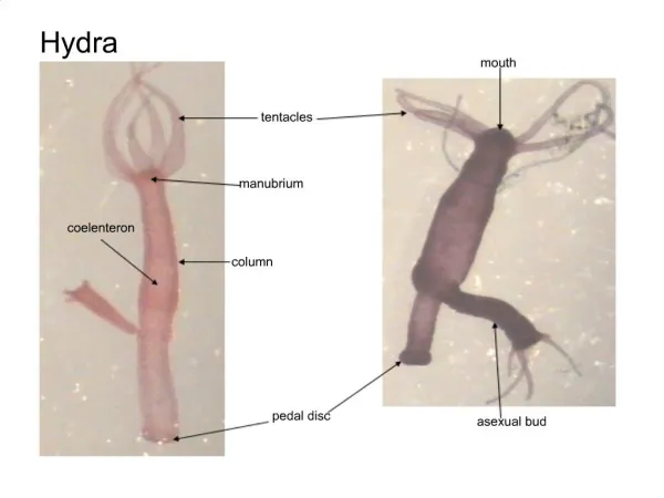
Hydra-Pneumatic 1. Hydra-Pneumatic hammer constitution Power head, hammer tup, piston rod, hammer body, tup guides, top pallet, bottom pallet. Power head including the main body, accumulator, buffer cylinder, gas cylinder, piston rod cylinder and bottom gland seal.
Third, unique feature 1.Eletro hydraulichammer constitution Hydra-Pneumatic 1)Upper tank This is a critical part of the hammer, it connects the hammer legs and holds the main components, comprising of control valve, oil discharge valve and safety valve.
Third, unique feature 1. Hydra-Pneumatic hammer constitution Hydra-Pneumatic 2)Accumulator (right) It is an indispensable part of the hammer it is divided into an upper gas chamber and a lower oil chamber by a piston. It is used for storing compressed gas and pressurized oil respectively .It provides pressurized oil for the fast movement of the hammer.
Third, unique feature 1. Hydra-Pneumatic hammer constitution Hydra-Pneumatic 3)Gas cylinder and oil cylinder (left) Oil cylinder having a piston inside is surrounded by a gas cylinder. The space between the two cylinders is filled with compressed nitrogen .The top of gas cylinder is open to the gas cylinder and the lower part of the oil cylinder is filled with pressurized oil .The pressure difference between oil and gas produces the hammer movement.
Third, unique feature 1. Hydra-Pneumatic hammer constitution Hydra-Pneumatic 4)Buffer cylinder It is a very important part for safety protection and is composed of; a cylinder , piston, cover and spring .There is low pressure nitrogen in the upper cavity . When the piston rod returns to the top of the gas cylinder too fast, its excess kinetic energy is absorbed so avoiding the cylinder cover breaking away and further damage
Third, unique feature 1. Hydra-Pneumatic hammer constitution Hydra-Pneumatic 5)Main gland seals They are important parts for sealing high pressure oil in the lower chamber of the oil cylinder and positioned at the bottom of upper tank .They are also the guide for piston rod. Seal of “high-low pressure combination” and fixation of “duplex clamping” have realized dual purpose of safety and reliability.
Hydra-Pneumatic Third, unique feature 1. Hydra-Pneumatic hammer constitution 6)Ram piston rod and their connection Ram and piston rod are designed and manufactured according to international standards to assure their strength and rigidity under alternating stress after long term use. The piston rod is reliable for five years under normal conditions. They are connected using a taper for convenient maintenance without damage to the ram.
Hydra-Pneumatic Third, unique feature 3. Electrical system characteristic Design purpose of the electronic system is “reasonable structure and advance performances for stable ,reliable running ,sensitive control ,low failure,long life”, All components are available locally. The electrical system meets all current EU directives.
Hydra-Pneumatic Fourth, The conversion process from air to Hydra-Pneumatic The process is that using hydraulic power head substitutes the original air cylinder with the power head, guides, pump station, electronic control system and nitrogen gas system.
Hydra-Pneumatic Fifth, Hydra-Pneumatic hammer safety systems The hydra-Pneumatic hammer is a high speed reciprocation unit that creates intense vibration, for the guaranteed of equipment under normal operation and man-machine security, we adopted a "quality first, safety first" principle, we have successfully developed many protective measures within the control system
Hydra-Pneumatic hammer safety technology introduction Hydra-hydraulic hammer safety measures • 1. Oil temperature over temperature with automatic cooling • Oil level monitoring automatic system shut down; • Filter blockage system; • All pumps are automatically monitored; • Pressure test automatic monitoring system; • Main gland seal leakage monitoring system; • Pipeline bursts protection system; • Hammer piston rod monitoring protection system.
5 Ton Arch Hammer Conversion Damping Cylinder Hydraulic Cylinder Electric Control Main Tank Bottom Gland seal Connecting Bolts Tup Slides High Pressure Gas Pipe Accumulator Main Operating Valve Quick Release Valve Oil Supply Pipe Oil Return Pipe Piston Rod Tup Operating Lever
Rigby Hammer Damping Cylinder Composed Cylinder Electrical control Main Tank Ram seal Ram Guides High Pressure Gas Pipe Accumulator Main Control Valve Oil Supply Pipe Oil Return Pipe Quick Release Valve Piston Rod Hammer Head Operating lever Cylinder Air Ports Piston Piston Rod Hammer head Upper Anvil
Hydra-pneumatic hammer Third, unique feature 2. Hydraulic pressure station characteristics Hydraulic station is a pressurized oil supply system for the storing and releasing high pressure oil. It includes oil tank , motor , Hydraulic pump , Hydraulic valve, refrigerator, Hydraulic oil , system of gas storage. The design purpose is “reasonable structure and advance performances for stable and reliable running
Hydraulic pump station Oil Tank High pressure feed pipe Electric heater High Pressure Oil Pipe Oil Return Port Unloading valve Pressure Gauge Pressure Switch Oil Suction Filter Hand operated Valve Hydraulic pump Motor And Coupling Oil Level And Thermometer Motor Bracket Motor Hydraulic Pump Plate type Strainer