Comprehensive Guide to Crafting Effective Project Reports and Presentations in Engineering Design
This guide is essential for documenting your team's project in Engineering Design. It outlines the critical components of a project report, emphasizing a consistent structure across reporting teams. Key sections include a cover page with essential project information, an introduction explaining your problem statement, design selection, detailed design descriptions with graphic illustrations, project schedules, and summaries. The document encourages professional presentation standards, use of high-quality graphics, and thorough proofreading to ensure clarity and effectiveness. Ideal for engineering students and professionals alike.

Comprehensive Guide to Crafting Effective Project Reports and Presentations in Engineering Design
E N D
Presentation Transcript
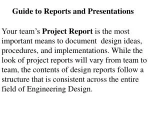
Guide to Reports and Presentations Your team’s Project Report is the most important means to document design ideas, procedures, and implementations. While the look of project reports will vary from team to team, the contents of design reports follow a structure that is consistent across the entire field of Engineering Design.
1. Cover page include the following: • The project title, the course and section numbers, the instructor's name, and the date. • Optional team picture with the names and e-mail links to each group member. • An abstract for the report (less than 150 words). • A Table of Contents with sections 1 through 8 as appropriate. • Date of submission (due date is 4/30, submit both hardcopy and Word file!
Reports • 1. Introduction • 2. Design Selection • 3. Design Description • 4. Design Features • 5. Prototype • 6. Project Schedule • 7. Project Summary and Conclusions • 8. References
Introduction • Discuss the problem statement your group has developed and the approach you've taken to solve the problem.
Design Selection • Discuss the process you went through in selecting your main design. How did you pick your design over the alternatives you'd developed?
Design Description • Describe the design approach that your group selected.
Design Description • Provide detailed 3-D drawings of your design prototype complete with appropriate labels and notes. • Provide only the views that best communicate your design. • Provide graphic illustrations where appropriate ( e.g. a program flow chart.) • MS Office and other software tools provide powerful presentation tools; use these features as you feel comfortable.
Design Features • List and discuss the features of your design. • Discuss the limitations or weaknesses of your design.
RCX Scooper Motor Rear Wheel Motors (2) Wheels Light Sensor Scooper Touch Sensor (both arms)
Prototype • Include images of the prototype with appropriate labels and notes • Provide detailed results of your analysis and testing, including any data that influenced the design's performance. • Describe how you performed your analysis. • Include any testing results you collected to optimize the performance.
Project Schedule • List Milestones of your progress throughout the semester • Team leader: Attach attendance log for all participants.
Project Summary • Distill the essence of the design (i.e., explain the uniqueness of the design and its strengths, and also how you would overcome the current weaknesses in the future).
Expectations • Graphics should be of high quality and effective in presenting the design. • Use proper English grammar and correct spelling, and be sure to proofread the report. Remember that this is a professional document. • Make your points concisely in well-ordered paragraphs. • Substantiate your discussion with insights and arguments.
Reports and Presentations: Each figure MUST have a number and title. Reference each figure in the report text. Fig.3 Challenger Booster
Presentations • Use Powerpoint if possible • Use graphics generously • Use the Lego camera to create movies. Embed the movie in your presentation.
Presentations Examples (From multiple reports)
Initial Design Ideas: Gear Ratio High point: High Torque (good for pushing) Tank Treads offer very good torque but low speed and maneuverability However the objective being survival, low maneuverability can become a problem Tank Style Gear Ratio
Final Design Idea: Four Wheel Drive Four Wheel Drive with motors against inside wall Two motors used to control movement One motor controls the ram Light sensor located on front left side Ultrasonic sensor located in middle at top
Final Design Idea: Four Wheel Drive Side View
Final Design Idea: Four Wheel Drive Gear Set-up The Gear Ratio is 1:3 And the torque at motor is 16.7Ncm. That leaves the robot with 16.7 X 1/3= 5.566 5.566Ncm. Of torque at each wheel
Final Design Idea: Sensors Ultrasonic Sensor: Located at the top of the robot. Light Sensor: Located on the interior left hand corner
Final Design Idea: Sensors Sensors placed in ideal areas, in these areas nothing can happen that will alter their function or decrease performance The only issue is that the ultrasonic sensor is located In an area where it may not be able to locate smaller robots.
Final Design Idea: Chassis The Wheels are the same size and equally spaced to allow for more traction in the four wheel drive gear system that is used Problems: when too much weight is placed on back or front, becomes two wheel drive system
Design Overview (High points) Overall stability, with decent torque, good weight distribution (Aprox. 50/50) Good maneuverability Programmed properly Box Chassis Low to the ground Exceptional pushing machine
Design Overview (Low points) Not maximum torque possible in a sumo-bot Not the most maneuverable Interior is small Ultrasonic sensor located in a position that is not beneficial against relatively smaller robots
Final Design: Sensors • The ultrasonic is located on the top in the center, right behind a wall, and the light sensor is tucked safely under the blade.
Final Design: Motors and Wheels • We decide to go for a mix between torque and speed, compromising for slightly more speed than torque. The wheels were chosen based on traction and compactness.
Final Design: Programming • The program features a loop which is based upon the light sensor. If the sensor detects nothing, then another loop based upon input from the ultrasonic is activated. If a target is located the robot drives forward and if none is found then, it circles until one is detected. • If at anytime the white line of the ring is detected by the light sensor, the robot will reverse a little and rotate 180 degrees then, continue on.
Final Design Summary • We have created a robot that has a very rigid/durable design, a perfect mix of torque and speed, that is able to get underneath opponents and that has adequate maneuverability. • However, some problems are present. The robot’s wheels at times get caught on other robots and the program is unable to center on targets, instead it merely waits and attacks in a general direction.