Hydrogeological Investigation of the Lower Floridan Aquifer (P280) Frostproof Site
This presentation summarizes Phase 1 results of the hydrogeological investigation of the Lower Floridan Aquifer at the Frostproof site in Florida. It covers drilling, lithology, groundwater elevations, water quality, hydraulic parameters, and next steps. The purpose was to assess raw water production, confinement between aquifers, and potential for concentrate disposal. Results show distinct flow zones, good confinement, and identified production and injection zones. The next steps involve monitoring well completion and further testing.

Hydrogeological Investigation of the Lower Floridan Aquifer (P280) Frostproof Site
E N D
Presentation Transcript
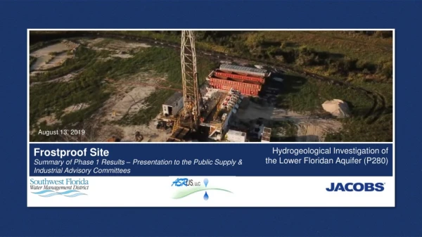
August 13, 2019 Hydrogeological Investigation of the Lower Floridan Aquifer (P280) Frostproof Site Summary of Phase 1 Results – Presentation to the Public Supply & Industrial Advisory Committees
AGENDA • Introduction and Background • Phase 1 • Purpose and Objectives • Phase 1 Drilling and Testing Program • Phase 1 Results • Lithology • Groundwater Elevations • Water Quality • Hydraulic Parameters • Monitoring Well Installation • Next Steps 2
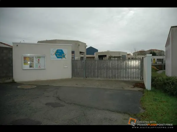
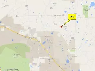
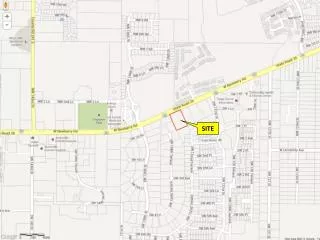
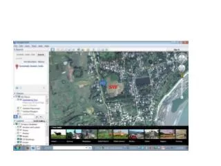
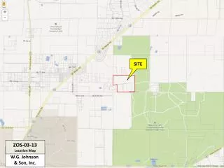
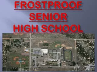
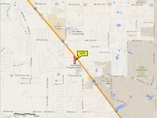
INTRODUCTION • Frostproof Site • One of three P280 LFA well drilling sites • Southern most site • Near Frostproof, FL 3
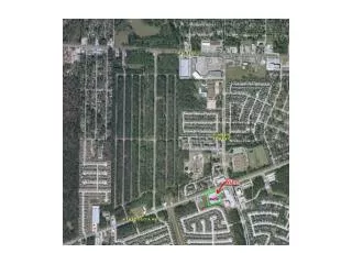
BACKGROUND HYDROGEOLOGY Approximate project location 5
Phase 1— Purpose & Objectives • Raw Water Production • Determine if the LFA can support future brackish water supply • Confinement • Determine if there is sufficient confinement between UFA/LFA • Concentrate Disposal • Determine if the LFA could support future injection wells for membrane concentrate disposal 6
Phase 1—Drilling & Testing Program • Monitoring Well Installation • Surficial aquifer (SAMW-1) • Upper Floridan aquifer (UFAMW-1) • Drilling • Drill to sub-Floridan confinement • Continuous lithologic sampling • Cores at four discrete depths • Groundwater Elevations • Geophysical and OBI Logging • Hydraulic and Water Quality Data • Incrementally during drilling • Packer Testing • 7 discrete depths • LFA Monitoring Well Completion • Dual zone monitoring, LFAI, LFAII(a) • Constant Rate Aquifer Tests • Water quality sampling 7
Phase 1—Groundwater Elevation (ft NAVD88) Intermediate casing installation Note: GWEs not corrected for salinity 10
Phase 1—Groundwater Elevation (ft NAVD88) Depth of Drilled Pilot Hole (ft bgs) <0.5 ft Note: GWEs not corrected for salinity Intermediate casing installation 11
UFA/LFA Groundwater Elevation Difference Note: GWEs not corrected for salinity Phase 1 Results—Vertical Flow Gradients • Graphic plots MZMW-1 GWE – UFAMW-1 GWE • Negative difference = downward vertical gradient • LFAI groundwater elevations similar to UFA groundwater elevations • Downward gradient after intermediate casing set • Interflow in the borehole affected water quality results Intermediate casing 12
MZMW-1 Drill Stem Water Quality Phase 1 Results—Water Quality • Downward flow in the borehole affected water quality results • Little variation observed between LFAII(a) and LFAII(b) due to intermixing • LFAII • Chloride ~70 mg/L • Sulfate ~ 1,800 mg/L • TDS ~ 3,000 mg/L Intermediate casing 13
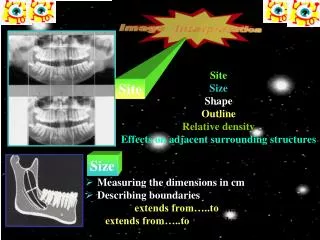
Phase 1 Results—Geophysics with Tentative Hydrogeologic Picks 14
Phase 1— Remaining Testing • LFA Monitoring Well Completion • Dual zone monitoring • Constant Rate Aquifer Tests • Pumping rate: ~200 – 500 gpm • LFA I • LFA II(a) • Monitoring zones: SA, UFA, LFA I, LFA II(a) • Water quality: primary, secondary, RO analytes • Lab permeabilities on core 16
Phase 1—Conclusions Water Supply Concentrate Disposal • Production zone in LFA II(a) • 3 gpm/ft, estimated • UFA/LFA confinement was identified • >500 ft thickness • Packer testing and flow compilation log suggest good confinement • No effects observed in UFA during testing program • Injection zone in LFA II(b) • 6 gpm/ft, estimated • Confinement between LFA II(a) and LFAII(b) • ~300 ft thickness • Geophysical logs suggest two distinct flow zones separated by confining interval 17
Next Steps at Crooked Lake/Frostproof/Lake Wales Crooked Lake • Construction on-going with dual zone LFA monitoring well Frostproof • Complete Phase 1 • Just kicked-off Phase 2 Lake Wales • Construction on-going with Phase 1 (similar to Frostproof testing) 18
Phase 1 Results—Lithology and Tentative Hydrogeologic Picks 600 9