Download
1 / 24
240 likes | 309 Views
This module integrates a switch, amplifier, attenuators, power detector, and bias tee for laser transmitter control. The prototype has a gain of ~50 dB with excellent stability and linearity. Temperature-regulated for performance across the 500 MHz – 10 GHz range.

E N D
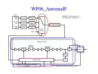
WP06_AntennaIF3 principal modules • switch • amplifier (= ATA ‘PAM’) • includes attenuators (0-60 dB), power detector, and bias tee for the laser transmitter • integrate with CANbus controller? • aluminum box; mount flange to temperature regulated plate, or if necessary to separate thermoelectric cooler • laser transmitter (= ATA ‘OTX’)
WP06_AntennaIF: amplifier module = ATA post-amp module • frequency range 500 MHz – 10 GHz • gain flat within ±3 dB across band • input noise temp < 1200 K • input pwr level –50 dBm to +10 dBm (!) • linearity better than 1% • gain stable to 1 part in 103, if temperature regulated to 0.1 C
amplifier module: gain compression ~ 1% at 1.5 dBm output power outputpwr gain, .02 dB/div input pwr swept from –60 dBm to –45 dBm
WP06_AntennaIFtemperature dependence of gain 0.3 dB / 20 C 0.4% / C gain stability of 10-3 requires ±0.1 C temp regulation high freq ripples due to poor output match
WP06_AntennaIF: optical transmitterNEC NX8560LJ 1550 nm DFB laser + electroabsorption modulator + TEC
WP06_AntennaIF: laser transmitter = ATA OTX module • includes: • NEC NX8560LJ • laser • EA modulator • thermoelectric cooler • photodiode power monitor • thermistor • TEC controller (5 V, ~ 1 amp) • laser current supply • modulator DC bias (bias tee located in amplifier module) • Photonics Inc will build 700 modules for ATA; cost approx $2.5 K each
WP06_AntennaIFopen questions • will detector on amplifier module be used for beamswitched continuum measurements? • if so, will switched-power demodulation be done at the IF CANbus node? how will mirror position be transmitted? • power supply: requires ~ 1 amp at 5 V; is it necessary to get this from 24 V dc-dc converter • can RF power damage the electroabsorption modulator; how to protect without compromising linearity?
WP02_LOreference key features • distributes two reference frequencies (1100-1260 MHz tunable, 10 MHz fixed) from control building to antennas via singlemode optical fiber • linelength system continuously monitors electrical delay through each fiber to an accuracy of ~0.1 picosec, approx 8° phase at 230 GHz • 1 pps tick distributed to antennas, as a missing pulse on the 10 MHz reference • allow for 3 subarrays operating with different reference frequencies
WP02_LOreferencecurrent BIMA fiber distribution approx 135 feet (200 nsec) of fiber exposed to outdoor air temp
linelength monitor via roundtrip phase • 135’ of fiber at outdoor air temp ( = 200 nsec) • ~ 2 psec/C • ~ 180°/C at 230 GHz
WP02_LOreferencelinelength options CPL TRX CPL TRX RX RX optical circulators • echo on same fiber • temperature coefficients of circulators? • reflections from bad connectors? • echo on 2nd fiber • do fiber lengths track each other?
WP02_LOreference: 3-fiber test echo from 1 antenna coupled back on 3 separate fibers: 3 independent measurements
WP02_LOreference: 3-fiber test 1 psec long term drifts due to cabin temp change 0.2 psec glitches during slew
example of linelength correction 3c454.3, 86 GHz, baseline 2-8, through sunrise linelength-corrected raw data
fiber photodiode probable explanation • gap acts like Fabry-Perot cavity; increasing temp expands gap, causes periodic variation in laser power at photodiode • laser power affects diode capacitance or resistance, hence changes phase of RF signal • substituting APC connector seems to cure the problem
WP02_LOreference • short term: with 10 MHz thermal problem fixed, reinstall on BIMA in November • longer term: • test optical circulators? • one laser/antenna to make subarrays easier? • convert to 1550 nm NEC lasers?