Ultrahigh Resolution 3D Model of Murine Heart Reconstruction
Robust algorithm for distortion-free ultrahigh-resolution 3D model reconstruction of a murine heart using CLSM images registered with micro-CT template. Method includes data acquisition with micro-CT and CLSM scans, image montaging, and volume reconstruction.

Ultrahigh Resolution 3D Model of Murine Heart Reconstruction
E N D
Presentation Transcript
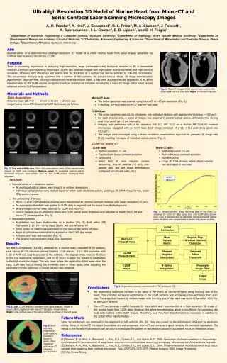
Fig. 1. Micro-CT images of the murine heart used in this study. Left. Vertical long axis. Right. Horizontal long axis. Fig. 2. Top and middle row. Short axis cross-section views of the murine heart imaged by CLSM and montaged. Bottom panel. 4x magnified septum wall in horizontal long-axis cross-section view of 33rd CLSM section displaying fiber alignment. Fig. 3. Volume profiles along the long axis of the heart (z) obtained for micro-CT data (blue line) and CLSM data (brown line). Loss of material due to vibratome slicing and CLSM optical plane thickness was compensated to match the volume profiles. Initial Estimation Mean Square Metric Regular Step Gradient Descent Optimizer Micro-CT Image (Binary) Nearest Neighbor Interpolator Centered Affine Transform CLSM Image (Binary) CLSM Image B-Spline Interpolator Resample Image Filter Fig. 4. Registration process implemented in ITK framework [3]. Output Image Fig. 5. Left. CLSM sections (numbers from top to bottom), shown in green; affine-registered with micro-CT template, shown in blue. Right. Long vertical view of the same sections as shown in the left panel. Fig. 6. Short axis view obtained for CLSM sections (numbers) shown in green; affine registered with micro-CT template shown in blue. Ultrahigh Resolution 3D Model of Murine Heart from Micro-CT and Serial Confocal Laser Scanning Microscopy Images A. H. Poddar1, A. Krol2, J. Beaumont2, R. L. Price3, M. A. Slamani4, J. Fawcett1, A. Subramanian1, I. L. Coman5, E. D. Lipson7, and D. H. Feiglin2 1Department of Electrical Engineering & Computer Science, Syracuse University; 2Department of Radiology; SUNY Upstate Medical University; 3Department of Developmental Biology and Anatomy, School of Medicine; 4ITT Industries, Advanced Engineering & Sciences; 5Department of Mathematics and Computer Science, Ithaca College; 6Department of Physics, Syracuse University; Aim Reconstruction of a distortion-free ultrahigh-resolution 3D model of a whole murine heart from serial images generated by confocal laser scanning microscopy (CLSM). Purpose There is increasing importance in analyzing high-resolution, large (centimeter-scale) biological samples in 3D in biomedical research. Confocal Laser Scanning Microscopy (CLSM) can generate images with high-spatial (sub-micrometer) and high-contrast resolution. However, light absorption and scatter limit the thickness of a section that can be scanned to 100–200 micrometers. This necessitates slicing a large specimen into a number of thin sections. We present here a robust, 3D image-reconstruction algorithm for distortion-free, ultrahigh resolution of the whole murine heart. It has been accomplished by application of an affine transformation to the CLSM volume to register it with an undeformed template provided by a micro-CT image of the intact sample obtained prior to CLSM preparation. Materials and Methods Data Acquisition A murine heart (3D FOV = ~10 mm × 10 mm × 10 mm) was imaged using micro-CT followed by CLSM techniques, as follows: Micro-CT Scan • The entire specimen was scanned using micro-CT at ~15 μm resolution (Fig. 1). • A SkyScan 1074 portable micro-CT scanner was used. CLSM Scan • The entire specimen was cut, by vibratome, into individual sections with appropriate thickness (~100 μm). • For each physical slice, a series of images was acquired in parallel optical planes, defined by the varying axial focal depth (at ~5 μm intervals). • Imaging was performed with a 4× objective (NA 0.2, WD 15.7) on a BioRad MRC1024 ES confocal microscope, equipped with an Ar/Kr laser. Each image consisted of a 512×512 pixel array (pixel size 4.83 μm2) • The images were montaged using a phase-correlation maximization algorithm to generate 3D image data [1-2], resulting in images of individual optical planes (Fig. 2). • CLSM vs. micro-CT • CLSM data: • Spatial resolution <1 µm • Excellent soft tissue contrast resolution • Destructive • Small field of view requires sample sectioning; loss of material (~5 µm); non-parallel cuts; and soft tissue deformations (collapsed or ruptured walls, etc.) • Micro-CT data: • Spatial resolution >5 µm • Poor soft-tissue contrast resolution • Nondestructive • Large 3D field-of-view; whole object volume can be imaged in one scan • Methods • Reconstruction of a vibratome section • All montaged optical planes were brought to uniform dimensions. • Individual optical planes were stacked together within each vibratome section, yielding a 3D (MHA image format, under ITK) section volume. • Pre-processing of images • Micro-CT and CLSM vibratome volumes were transformed to common isotropic matrices with lower resolution (20 µm). • An appropriate threshold was applied to CLSM data to segment out the tissue from the background. • Binary image volumes were obtained for CLSM and micro-CT. • Loss of material due to vibratome slicing and CLSM optical plane thickness were adjusted to match the CLSM and micro-CT volume profiles (Fig. 3). • Registration process • Registration has been implemented as a pipeline (Fig. 4), built within ITK Framework [3] in C++ using Visual Studio .Net and Windows XP. • Initial center of rotation was estimated on the basis of the center of mass. • Angle of rotation was estimated by a search in the 0-360 deg range. • A registration loop was executed (Fig. 4). • The original high-resolution image was resampled. Results Our test CLSM dataset (1.6 GB), obtained for a murine heart, consisted of 50 sections, each having 30–35 individual planes (totaling 1,418 planes). A 1.5 GHz computer with 1 GB of RAM was used to process all the sections. The elapsed times were a) 45 hours to find the registration parameters, and b) 33 hours to apply the transform parameters to the high-resolution image. The only cases where the registration failed were when the input CLSM data had a missing tile. However, even in those cases, after adjusting the parameters for the optimizer, a correct solution was obtained. • Conclusions • We observed a monotonic increase in the value of the metric as we move higher along the long axis of the heart. This indicates increasing deformation in the CLSM sections with increasing cross-sectional (short axis) size. The angle that the axis of rotation makes with the long axis of the heart was found to be within ±0.2ofor all the CLSM sections. • Micro-CT can serve as a useful template for registration and reconstruction of a high-resolution 3D image of the murine heart from CLSM data. However, the affine transformation alone is insufficient for correcting the local deformations in the CLSM images. Therefore, local free-form transformation is necessary in addition to the global affine transformation. Future Work Some inconsistencies are observed in the alignment of left ventricle (Fig. 6). They are caused by the deformation produced by vibratome slicing. Since, in micro-CT, the object boundaries are well-preserved, micro-CT can serve as a good template for nonrigid registration. The trends in the transform parameters can be used to investigate the pattern of deformation caused in successive slices by vibratome action. References [1] Slamani, A.-M., Krol, A., Beaumont, J., Price, R. L., Coman, I. L., and Lipson, E. D. 2005. Application of phase correlation to the montage synthesis and 3D reconstruction of large tissue volumes from confocal laser scanning microscopy, Microscopy and Microanalysis, in press. [2] Slamani, A.-M., Krol, A., Beaumont, J., Price, R. L., Coman, I. L., and Lipson, E. D. 2004. Three-dimensional reconstruction of large tissue volumes from scanning laser confocal microscopy. Proc. SPIE 5370:1972-1979 (Medical Imaging 2004: Image Processing) [3] http://www.itk.org