Download

1 / 40
400 likes | 492 Views
Learn about the non-destructive methods for recovering the spatial-temporal structure of ocean surface waves using the Polarimetric Slope Sensing (PSS) technique. Understand the importance of passive optical techniques, characteristics of polarized light, and how the PSS technique helps in imaging through waves. Explore the detailed process of building and testing an imaging polarimeter for oceanographic applications, including sample results and comparisons with published data. Discover the concept of optical flattening to remove distortions caused by surface waves for clear imaging. Join the efforts in seeing through waves for sub-surface to surface imaging with real-time processing. Dive deep into the world of oceanography with cutting-edge technology.

E N D
Nondestructive Methods for Recovering the Spatial- Temporal Structure of Ocean Surface Waves & Seeing Through Waves Howard Schultz <hschultz@cs.umass.edu> Chris J. Zappa, Michael L. Banner, Larry Pezzaniti August 2010
Outline • Why recover the 2-D spatial-temporal structure of the ocean surface? • Requirements • Why use a passive optical technique • What is polarimetry? • What is the Polarimetric Slope Sensing (PSS) technique? • Build and Test an Imaging Polarimeter for Ocean Apps. • Recent Experiment and Results • Optical Flattening • Seeing Through Waves
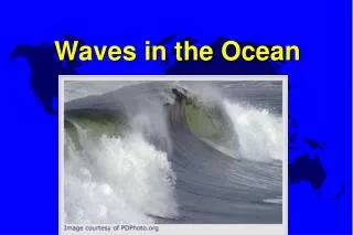
Why recover the 2-D structure of the ocean surface? • Characterize small scale wave dynamics • Air-sea interactions occur at short wavelengths • Non-linear interaction studies require phase-resolved surface topography • Enable through-the-wave imaging • Requirements • Spatial resolution (resolve capillary waves) ~ 1mm • Temporal resolution ~60Hz sampling rate • Shutter speed < 1 msec • Why use a passive optical technique • Probes disturb the air-sea interaction • Radar do not produce phase-resolved surfaces • Active techniques are complex and expensive
What is polarimetry? • Light has 3 basic qualities • Color, intensity and polarization • Humans do not see polarization
Linear Polarization http://www.enzim.hu/~szia/cddemo/edemo0.htm
Amount of circular polarization Orientation and degree of linear polarization Intensity What is polarimetry? • A bundle of light rays is characterized by intensity, a frequency distribution (color), and a polarization distribution • Polarization distribution is characterized by Stokes parameters S = (S0, S1, S2, S3) • The change in polarization on reflection or scattering is governed by Muller Calculus SOUT = M SIN • Where M contains information about the shape and material properties of the scattering media • The goal: Measure SOUT and SIN and infer the parameters of M Incident Light Muller Matrix Scattered Light
What is the Polarimetric Slope Sensing (PSS) technique? • Use the change in polarization of reflected skylight to infer the 2D surface slope for every pixel in the imaging polarimeter’s field-of-view
How well does the PSS technique work? • Conduct a feasibility study • Rented a linear imaging polarimeter • Laboratory experiment • setup a small 1m x 1m wavetank • Used unpolarized light • Used wire gauge to simultaneously measure wave profile • Field experiment • Collected data from a boat dock • Overcast sky (unpolarized) • Used a laser slope gauge
Looking at 90 to the waves Looking at 45 to the waves Looking at 0 to the waves
X-Component Y-Component Slope in Degrees
X-Component Y-Component Slope in Degrees
Build and Test an Imaging Polarimeter for Oceanographic Applications • Funded by an ONR DURIP • Frame rate 60 Hz • Shutter speed as short as 10 μsec • Measure all Stokes parameters • Rugged and light weight • Deploy in the Radiance in a Dynamic Ocean (RaDyO) research initiative http://www.opl.ucsb.edu/radyo/
Camera 3 Camera 4 Camera 1 (fixed) Polarizing beamsplitter assembly Objective Assembly Camera 2 Motorized Stage 12mm travel 5mm/sec max speed
FLIP INSTRUMENTATION SETUP Scanning Altimeters Visible Camera Air-Sea Flux Package Infrared Camera Polarimeter
Sample Results • A sample dataset from the Santa Barbara Channel experiment was analyzed • Video 1 shows the x- and y-slope arrays for 1100 frames • Video 2 shows the recovered surface (made by integrating the slopes) for the first 500 frames • A statistical comparison between our results and published results is given as well
X and Y Slope Video Show the video http://vis-www.cs.umass.edu/~hschultz/WaveTank/2008_Run42_XandYSlopes_Cam4_Frames8891-10152_w_trailer-1.wmv
Reconstructed Surface Video Show the video http://vis-www.cs.umass.edu/~hschultz/WaveTank/Z_movie.mpg
Seeing Through Waves • Sub-surface to surface imaging • Surface to sub-surface imaging
Optical Flattening • Remove the optic distortion caused by surface waves to make it appear as if the ocean surface was flat • Use the 2D surface slope field to find the refracted direction for each image pixel • Refraction provides sufficient information to compensate for surface wave distortion • Real-time processing
Image FormationSubsurface-to-surface Observation Rays Air Water Imaging Array Exposure Center
Image Formationsurface-to-subsurface Exposure Center Imaging Array Air Imaging Array Water Exposure Center
Optical Flattening Algorithm • Collect polarimetric images • Compute the Stokes parameters for each pixel • Recover the 2D surface slope field • Compute the refraction for each rays as it passes through the air-sea interface • Create an undistorted image
Un-distortionA lens maps incidence angle θ to image position X θ Lens Imaging Array X
Un-distortionA lens maps incidence angle θ to image position X θ Lens Imaging Array X
Un-distortionA lens maps incidence angle θ to image position X Lens Imaging Array X
Un-distortionA lens maps incidence angle θ to image position X θ Lens Imaging Array X
Un-distortionA lens maps incidence angle θ to image position X θ Lens Imaging Array X
Un-distortionUse the refraction angle to “straighten out” light rays Distorted Image Point Image array Air Water
Un-distortionUse the refraction angle to “straighten out” light rays Un-distorted Image Point Distorted Image Point Image array Air Water
Real-time Un-Distortion • The following steps are taken Real-time Capable • Collect Polarimetric Images ✔ • Convert to Stokes Parameters ✔ • Compute Slopes (Muller Calculus) ✔ • Refract Rays (Lookup Table) ✔ • Remap Rays to Correct Pixel ✔
Detecting Submerged Objects“Lucky Imaging” • Use refraction information to keep track of where each pixel (in each video frame) was looking in the water column • Build up a unified view of the underwater environment over several video frames • Save rays that refract toward the target area • Reject rays that refract away from the target area
For more information contact Howard Schultz University of Massachusetts Department of Computer Science 140 Governors Drive Amherst, MA 01003 Phone: 413-545-3482 Email: hschultz@cs.umass.edu