Download
1 / 38
420 likes | 960 Views
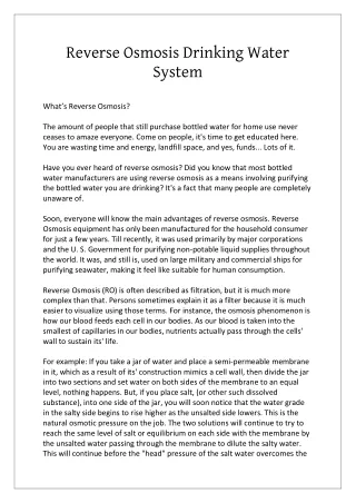
Reverse Osmosis Water System And Its Technologies . Chemistries and Physics of Water Purification. Contaminants in Water Water Purification Technologies. Contaminants In Water. Water Purification Technologies. Water Purification Technologies. Ultra filtration Ultraviolet Storage Tank

E N D
Contaminants in Water • Water Purification Technologies
Water Purification Technologies Ultra filtration Ultraviolet Storage Tank Distribution Loops Distillation • Filtration • Chlorine removal • Scale Control • Reverse Osmosis • Ion Exchange
Filtration • Depth Filters - Entrapment • Screen Filters - Sieving, • Membranes
Depth Filter • Media • Cotton Fibers, Glass Fibers • Polypropylene, Nylon • Filaments, Sand Grains • Pore Rating • Nominal (98% Removal) • Range • 0.5-1000um or combinations • Thickness • 10-30mm
Membrane Micro Filter • Media • Nylon, • Teflon, Cellulose • Esters • Pore Rating • Absolute (100% • Removal) • Range • 0.1 to 10 um • Thickness • 150um
Chlorine Removal Activated Carbon • Raw Materials • Coconut Shell, • Wood, Lignite • Oil / Plastic • Activation • Heat, Chemical • Activation generates a highly porous structure with a large surface area for Wood, Lignite. • Surface area • 1000 m2 /gram • Activated Carbon • Bead Remove Chlorine Remove Organics
Sodium Bisulfite • Sodium Bisulfite (NaHSO3) is a reducing agent capable of dechlorinating the feed water to a Reverse Osmosis System. • Dechlorination reactions NaHSO3+ CL2+ H2O NaHSO4+ 2HCl • 1ppm of chlorine (CL2) requires 1.46 ppm of NaHSO3 • To ensure complete Dechlorination Add 10% excess of sodium bisulphite
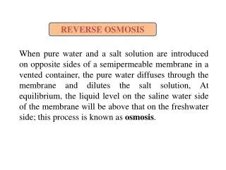
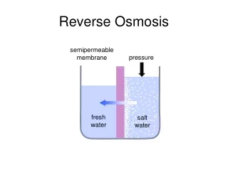
Low pressure High pressure Feed water under pressure Semi-permeable membrane Purified water raw water Reject water Permeate water drain or recycle Reverse osmosis (RO) theory
Thin Film Composite Membrane Thin Film Layer Support Structure
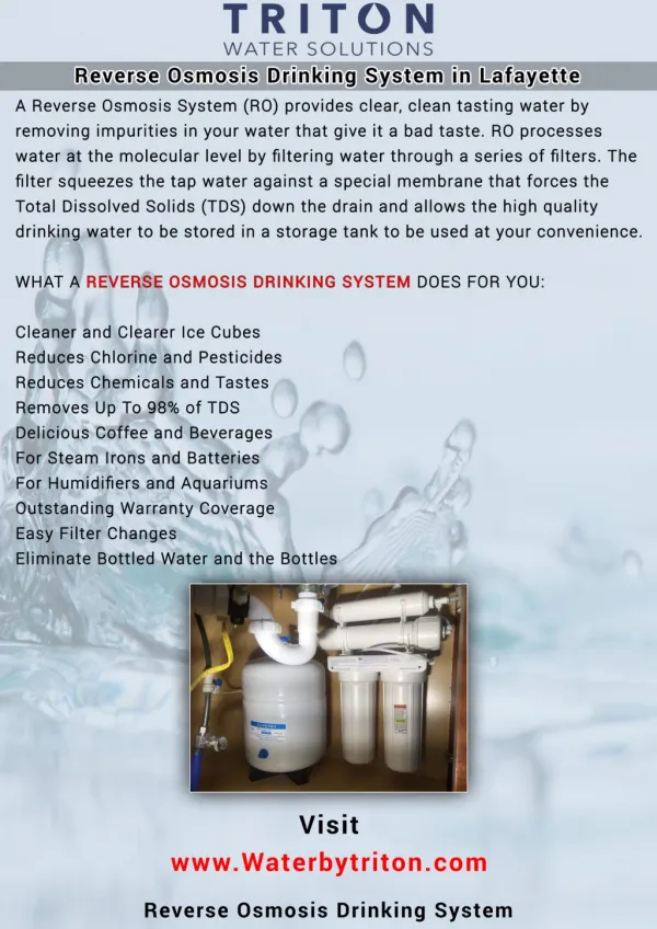
Reverse Osmosis • Performance • 95 - 99% Rejection of Inorganic Ions • 99% Rejection of Organics • 99% Rejection of Particles and Microorganisms • Recovery • 10 - 65% of Feed Water
Ultra-Filtration • Can be used for WFI or for Water For Final Rinsing for parenteral manufacturing (if permitted) • Removes organic contaminants, such asendotoxins • Operation at 80°C, and sterilization at 121 °C
Oxidation of Organic Compound • HCHO + 2OH. UV HCOOH + H2O Formaldehyde Formic Acid + Water • HCOOH+2OH. UV CO2 + 2H2O FORMIC ACID CORBONDIOXIDE+WATER
Storage Tank • Design Considerations • Sized with Make-Up system • Store water protected from bacterial growth • Vent filter • Sanitary Overflow • Tank UV light or Spray Ball • Conical bottom • Steam or Ozone sterilization • Rupture Disk should always have monitor • Smaller the better
Hydrophobic air filter & burst disc Feed Water Cartridge filter 1 µm Spray ball Water must be kept circulating Optional in-line filter 0,2 µm UV light Outlets Hygienic pump Typical Water Storage And Distribution Schematic
D Flow direction arrows on pipes are important Deadleg section X <2D If D=25mm & distance X isgreater than 50mm, we have a dead leg that is too long. Sanitary Valve Water scours deadleg Distribution Loops • There should be no dead legs Ball valves are unacceptable Bacteria can grow when the valve is closed The water is contaminated as it passes through the valve Stagnant water inside valve