Download
1 / 47
470 likes | 614 Views
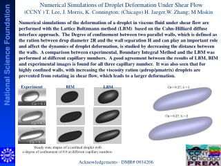
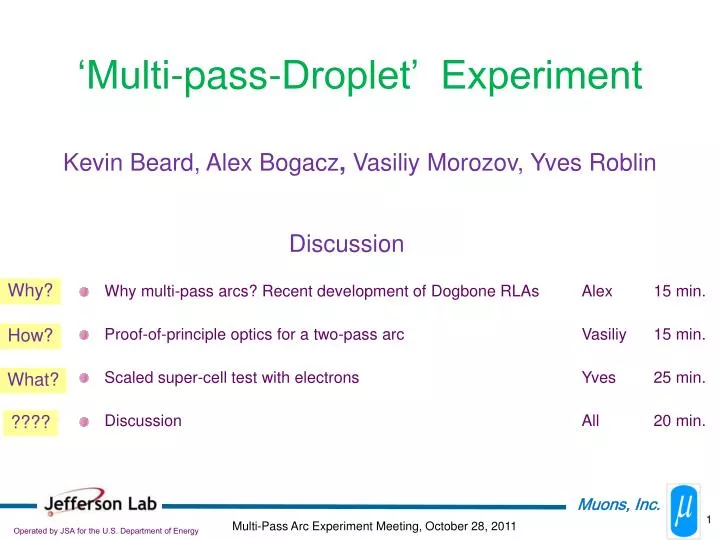
‘Multi-pass-Droplet’ Experiment. Kevin Beard, Alex Bogacz , Vasiliy Morozov, Yves Roblin. Discussion. Why multi-pass arcs? Recent development of Dogbone RLAs Alex 15 min. Proof-of-principle optics for a two-pass arc Vasiliy 15 min.

E N D
‘Multi-pass-Droplet’ Experiment Kevin Beard, Alex Bogacz, Vasiliy Morozov, Yves Roblin Discussion • Why multi-pass arcs? Recent development of Dogbone RLAs Alex 15 min. • Proof-of-principle optics for a two-pass arc Vasiliy 15 min. • Scaled super-cell test with electrons Yves 25 min. • Discussion All 20 min. Why? How? What? ????
Why multi-pass arcs? Recent development of Dogbone RLAs Alex Bogacz
A Decade of Muon RLAs • Racetrack RLA – NF Study I (2000) (Bogacz/Lebedev) • Switchyard (single bend, horizontal) • Individual energy return Arcs for recirculation • Dogbone RLA – NF Study II (2005) (Bogacz) • Better separation of passes • Compact arcs, saving on beamlines • Simultaneous acceleration of both charge species • Increasing number of passes (ISS/IDS-NF): • Bi-sected linac Optics (2006) (Bogacz) • Ramped linac quads (2007) (Johnson) • Reducing number of return Arcs – Multi-pass Arcs (IDS-NF): • Non-scaling FFAG arcs with sextupoles (2008) (Trbojevic/Bogacz/Wang) • Linear Non-scaling FFAG arcs (2010) (Morozov) • Arcs based on combined function magnets (2011) (Morozov)
Racetrack vs ‘Dogbone’ RLA DE/2 DE DE/2 2.5 DE • the droplets can be reduced in size according to the required energy • better orbit separation at linac’s end ~ energy difference between consecutive passes (2DE) • allows both charges to traverse the Linac in the same direction (more uniform focusing profile) • both charge signs can be made to follow a Figure-8 path (suppression of depolarization effects) DE 4
Dogbone RLA – IDS 900 MeV 244 MeV 0.9 GeV 3.6 GeV 86 m 0.6 GeV/pass
Pre-Linac and RLA I to RLA II … 244 MeV 3 GeV 900 MeV 1.8 GeV 1.2 GeV 2.4 GeV 3.6 GeV 6
Injection/Extraction Chicane FODO lattice: 900/900 (h/v) betatron phase adv. per cell 7
Droplet Arcs top view 1.2 GeV 2.4 GeV side view 1.2 GeV 1 m 2.4 GeV
Mirror-symmetric ‘Droplet’ Arc – Optics 3 20 BETA_X&Y[m] DISP_X&Y[m] -3 0 0 BETA_X BETA_Y DISP_X DISP_Y 130.618 (bout = bin and aout = -ain , matched to the linacs) disp. sup. cells out 2 empty transition cells disp. sup. cells out 2 empty transition cells 10 cells in 2 vertical steps 2 vertical steps
Switchyard - Arc 1 and 3 1.2 GeV 2.4 GeV 1.2 GeV
Switchyard - Arc 1 and 3 1.2 GeV 2.4 GeV 1.2 GeV
Multi-pass Linac Optics – Bi-sected Linac 5 15 BETA_X&Y[m] DISP_X&Y[m] 0 0 0 BETA_X BETA_Y DISP_X DISP_Y 39.9103 5 15 BETA_X&Y[m] DISP_X&Y[m] 0 0 0 BETA_X BETA_Y DISP_X DISP_Y 78.9103 ‘half pass’ , 900-1200 MeV initial phase adv/cell 90 deg. scaling quads with energy 6 meter 90 deg. FODO cells 17 MV/m RF, 2 cell cavities quad gradient 1-pass, 1200-1800 MeV mirror symmetric quads in the linac quad gradient
5 30 BETA_X&Y[m] DISP_X&Y[m] 0 0 0 BETA_X BETA_Y DISP_X DISP_Y 389.302 Multi-pass bi-sected linac Optics bx = 13.0 m by = 14.4 m ax=-1.2ay=1.5 bx = 7.9 m by = 8.7 m ax=-0.8ay=1.3 Arc 2 Arc 3 Arc 4 Arc 1 bx = 6.3 m by = 7.9 m ax=-1.2ay=1.3 bx,y → bx,y axy → - axy bx = 3.2 m by = 6.0 m ax=-1.1ay=1.5 bx,y → bx,y axy → - axy bx,y → bx,y axy → - axy bx,y → bx,y axy → - axy quad grad. 3.0 GeV 0.9 GeV 1.2 GeV 1.8 GeV 2.4 GeV 3.6 GeV length
100 5 BETA_X&Y[m] DISP_X&Y[m] 0 0 0 BETA_X BETA_Y DISP_X DISP_Y 254.651 100 5 DISP_X&Y[m] BETA_X&Y[m] 0 0 0 BETA_X BETA_Y DISP_X DISP_Y 254.651 ‘Fixed’ vs ‘Pulsed’ linac Optics (8-pass) Fixed Pulsed
A Decade of Muon RLAs • Racetrack RLA – NF Study I (2000) (Bogacz/Lebedev) • Switchyard (single bend, horizontal) • Individual energy return Arcs for recirculation • Dogbone RLA – NF Study II (2005) (Bogacz) • Better separation of passes • Compact arcs, saving on beamlines • Simultaneous acceleration of both charge species • Increasing number of passes (ISS/IDS-NF): • Bi-sectedlinac Optics (2006) (Bogacz) • Ramped linac quads (2007) (Johnson) • Reducing number of return Arcs – Multi-pass Arcs (IDS-NF): • Non-scaling FFAG arcs with sextupoles (2008) (Trbojevic/Bogacz/Wang) • Linear Non-scaling FFAG arcs (2010) (Morozov) • Arcs based on combined function magnets (2011) (Morozov)
2-pass ‘Droplet’ Arc • Dipole and quadrupole field components of the remaining magnets adjusted so that at both momenta • Each super-cell has periodic solutions for the orbit and the Twiss functions • At the cell’s entrance and exit, periodic orbit offset, dispersion and their slopes are all zero Vasiliy Morozov * Trajectories are shown to scale
Proof-of-principle optics for a two-pass arc VasiliyMorozov
RLA with Two-Pass Arcs Alex Bogacz RLA with FFAG Arcs 0.9 GeV 244 MeV 146 m 79 m 79 m 0.6 GeV/pass 3.6 GeV 264 m 12.6 GeV 2 GeV/pass • Two or potentially more regular droplet arcs replaced by one multi-pass arc • Simplified scheme • No need for a complicated switchyard • Compactness • More efficient use of RF by maximizing the number of passes • Potentially cheaper • Potential for other applications 19
Schematic Layout of a Two-Pass FFAG Arc simple closing of geometry when using similar cells = 41.3 m 300 60 C = 302.4 m 20
Non-Linear FFAG: 1.2 GeV/c Linear Optics of Unit Cell • Combined-function bending magnets are used • 1.2 GeV/c orbit goes through magnet centers • Linear optics controlled by quadrupole gradients in symmetric 3-magnet cell • Dispersion compensated in each 3-magnet cell 3-magnet cell in + out + in = in MAD-X (PTC) 21
Non-Linear FFAG: 2.4 GeV/c Linear Optics of Unit Cell • Unit cell composed symmetrically of three 3-magnet cells • Off-center periodic orbit • Orbit offset and dispersion are compensated by symmetrically introducing sextupole and octupole field components in the center magnets of 3-magnet cells sextupole and octupole components symmetric unit cell MAD-X (PTC) 22
Cell Matching • 1.2 GeV/c • 2.4 GeV/c outward inward outward inward 23
Issues with Non-Linear FFAG Arcs • Small dynamic aperture and momentum acceptance • Compensation of non-linear effects is complicated • Matching to linac is difficult • Hard to control the orbit lengths and therefore the difference in the times of flight of the two momenta • Combined function magnets with precise control of field components up to octupole 24
Two-Pass Linear FFAG Arcs • Same concept as with the non-linear FFAG arcs • Droplet arcs composed of symmetric FFAG cells • Each cell has periodic solution for the orbit and the Twiss functions • For both energies, at the cell’s entrance and exit: • Offset and angle of the periodic orbit are zero • Alpha functions are zero • Dispersion and its slope are zero • Outward and inward bending cells are automatically matched 25
Two-Pass Linear FFAG Arcs • Combined function magnets with dipole and quadrupole field components only • Much greater dynamic aperture expected than in the non-linear case • Easier to adjust the pass length and the time of flight for each energy • Easier to control the beta-function and dispersion values • Initial beta-function values chosen to simplify matching to linac • Much simpler practical implementation without non-linear fields • More elements are used in each unit cell to satisfy the diverse requirements and provide enough flexibility in the orbit control 26
Linear FFAG: Linear Optics of Unit Cell • Initial conditions set; orbit, dispersion and -function slopes zero at the center • Path lengths adjusted to give time of flight difference of one period of RF • 1.2 GeV/c • 2.4 GeV/c 27
DesignBased on Linear Combined-Function Magnets • Same concept as the linear FFAG design • Linear combined-function magnets • Droplet arc composed of symmetric super cells • Each super-cell has periodic solutions for the orbit and the Twiss functions • At the cell’s entrance and exit, periodic orbit offset, dispersion and their slopes are all zero • Two cells bending in the same or opposite directions automatically matched at both momenta • First few magnets of the super cell have dipole field component only, serving as spreader/recombiner • Both dipole and quadrupole field components of the remaining magnets used as parameters to meet the constraints • Synchronization with linac accomplished using path-length adjusting chicanes and/or vertical beam bypasses 29
Advantages of New Arc Design • All the advantages of a linear FFAG at a greater compactness • Alternating in-out-in or out-in-out pattern no longer required • Variation of the bending angles increases the number of available parameters and reduces the number of magnets required • Reduced orbit excursion • Spreader/recombiner incorporated into the arc design • Large dynamic aperture and momentum acceptance expected • Simple linear combined-function magnet design 30
300 60 C = 117.6 m Arc Layout • Still simple closing of arc geometry when using similar super cells • 1.2 / 2.4 GeV/c arc design used as an illustration can be scaled/optimized for other momenta preserving the factor of 2 momentum ratio of the two passes 31
Super-Cell Optics for P2 / P1 = 2 • P • 2xP 32
Droplet Arc Spreader/Recombiner • First few magnets of the super cell have dipole field component only, serving as Spreader/Recombiner * Trajectories are shown to scale 33
Two 2-Pass Arc Switchyard • Two 2-pass arcs • Lower momentum arc is the most challenging because of the highest momentum ratio; have a solution but still plenty of room for optimization * Trajectories are shown to scale 34
Future Studies and Optimization Paths • Lower momentum ratio • In case of a race-track design or in the inner droplet super cells, quadrupole field component can be used in the super-cell’s first magnets • Introduce sextupole component in the spreader/recombiner to control orbit deviation • Study the possibility of more than two passes • Study sextupole compensation of chromatic effects • Study error sensitivity • Tracking using realistic field maps 35
Scaled super-cell test with electrons Yves Roblin
goal of the project • Validate the concept of combined function magnet return arcs • Demonstrate feasibility, establish leadership • The scaled down test is a fertile ground for beam physics: • Dynamic aperture, • Effect of non linearities, • Tunability, • Envelope control, • Exploring the range of momenta that can be transported • Etc..etc.. 37
Closed orbit in cell 20cm aperture 38
scope • Build a fully functional half-cell (first phase) and eventually a full arc using electrons rather than muons. • Use this arc to characterize and demonstrate the concept for the MAP program • Great teaching tool. Can partner with local universities (ODU Beam physics program) 39
feasibility • Electron is 206 times lighter than muon. We only need a few MeV to 10’s of MeV to carry out the tests. Canonical 2.4 GeV/c lattice requires 11.6 MeV/c electrons. • Real arc will have superconducting magnets. We can build small normal conducting magnets in house to test the concept (more about this later) • We have the expertise with electron beams and can deliver the needed beam • We have the room at JLAB (see next slides) for testing a half cell, maybe even a full cell and later a full arc. 40
Testing a Half-Cell with Electrons Cell with 12 combined function magnets bending a totalof 30 degrees. Each magnet is a dipole+quad+sextupole. L=50cm, aperture=20cm Need instrumentation between each magnet (beam position monitors and means of measuring beam profile at some locations) Low current is adequate. 5 to 40 MeV/c of electron beam is good 41
Footprint of the apparatus Full cell About 8x3 meters on floor for the half cell. 42
Possible Locations at Jefferson Lab Where 0L07 spectrometer is. In a Hall after setting up CEBAF in energy recovery mode to get a Low energy beam. Good option if one want to test a bigger device. In the test lab !! Using the injector group test gun along with a cavity to bring beam to 5 MeV. Maybe some paperwork involved.. 43
Magnet specifications Aperture of 20 cm, length of 50 cm. The real thing will have to provide around 1.8 Tesla. Our prototype only needs to put out 1.8/206 or about 87 Gauss. These magnets can be easily (maybe??) made in house. 44
Printed Circuit design(cont) And it works.. Phys. Rev. ST Accel. Beams 3, 122401 (2000) 45
Printed Circuit design That’s a quad ! Back Front 46
Full scaled down simulation of RLA with return arcs Eventually two of these return arcs can be build. A small recirculating linac would accelerate from 11.6 GeV to 46.4 GeV/c over several recirculations. This would be a full scaled down test of the neutrino factory and/or muon colliders. 47