Download
1 / 46
470 likes | 687 Views
CS252 Graduate Computer Architecture Lecture 16 Memory Technology (Con’t) Error Correction Codes. John Kubiatowicz Electrical Engineering and Computer Sciences University of California, Berkeley http://www.eecs.berkeley.edu/~kubitron/cs252. Reducing hit time Small and simple caches

E N D
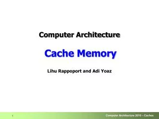
CS252Graduate Computer ArchitectureLecture 16Memory Technology (Con’t)Error Correction Codes John Kubiatowicz Electrical Engineering and Computer Sciences University of California, Berkeley http://www.eecs.berkeley.edu/~kubitron/cs252
Reducing hit time Small and simple caches Way prediction Trace caches Increasing cache bandwidth Pipelined caches Multibanked caches Nonblocking caches Reducing Miss Penalty Critical word first Merging write buffers Reducing Miss Rate Victim Cache Hardware prefetching Compiler prefetching Compiler Optimizations Review: 12 Advanced Cache Optimizations cs252-S09, Lecture 16
Review: Main Memory Background • Performance of Main Memory: • Latency: Cache Miss Penalty • Access Time: time between request and word arrives • Cycle Time: time between requests • Bandwidth: I/O & Large Block Miss Penalty (L2) • Main Memory is DRAM: Dynamic Random Access Memory • Dynamic since needs to be refreshed periodically (8 ms, 1% time) • Addresses divided into 2 halves (Memory as a 2D matrix): • RAS or Row Address Strobe • CAS or Column Address Strobe • Cache uses SRAM: Static Random Access Memory • No refresh (6 transistors/bit vs. 1 transistorSize: DRAM/SRAM 4-8, Cost/Cycle time: SRAM/DRAM 8-16 cs252-S09, Lecture 16
DRAM Architecture bit lines word lines Col. 1 Col.2M Row 1 N Row Address Decoder Row 2N Memory cell(one bit) M N+M Column Decoder & Sense Amplifiers D Data • Bits stored in 2-dimensional arrays on chip • Modern chips have around 4 logical banks on each chip • each logical bank physically implemented as many smaller arrays cs252-S09, Lecture 16
Review:1-T Memory Cell (DRAM) • Write: • 1. Drive bit line • 2.. Select row • Read: • 1. Precharge bit line to Vdd/2 • 2.. Select row • 3. Cell and bit line share charges • Very small voltage changes on the bit line • 4. Sense (fancy sense amp) • Can detect changes of ~1 million electrons • 5. Write: restore the value • Refresh • 1. Just do a dummy read to every cell. row select bit cs252-S09, Lecture 16
DRAM Capacitors: more capacitance in a small area • Trench capacitors: • Logic ABOVE capacitor • Gain in surface area of capacitor • Better Scaling properties • Better Planarization • Stacked capacitors • Logic BELOW capacitor • Gain in surface area of capacitor • 2-dim cross-section quite small cs252-S09, Lecture 16
DRAM Operation: Three Steps • Precharge • charges bit lines to known value, required before next row access • Row access (RAS) • decode row address, enable addressed row (often multiple Kb in row) • bitlines share charge with storage cell • small change in voltage detected by sense amplifiers which latch whole row of bits • sense amplifiers drive bitlines full rail to recharge storage cells • Column access (CAS) • decode column address to select small number of sense amplifier latches (4, 8, 16, or 32 bits depending on DRAM package) • on read, send latched bits out to chip pins • on write, change sense amplifier latches. which then charge storage cells to required value • can perform multiple column accesses on same row without another row access (burst mode) cs252-S09, Lecture 16
RAS_L CAS_L WE_L OE_L A 256K x 8 DRAM D 9 8 RAS_L DRAM Read Timing (Example) • Every DRAM access begins at: • The assertion of the RAS_L • 2 ways to read: early or late v. CAS DRAM Read Cycle Time CAS_L A Row Address Col Address Junk Row Address Col Address Junk WE_L OE_L D High Z Junk Data Out High Z Data Out Read Access Time Output Enable Delay Early Read Cycle: OE_L asserted before CAS_L Late Read Cycle: OE_L asserted after CAS_L cs252-S09, Lecture 16
Main Memory Performance • DRAM (Read/Write) Cycle Time >> DRAM (Read/Write) Access Time • 2:1; why? • DRAM (Read/Write) Cycle Time : • How frequent can you initiate an access? • Analogy: A little kid can only ask his father for money on Saturday • DRAM (Read/Write) Access Time: • How quickly will you get what you want once you initiate an access? • Analogy: As soon as he asks, his father will give him the money • DRAM Bandwidth Limitation analogy: • What happens if he runs out of money on Wednesday? Cycle Time Access Time Time cs252-S09, Lecture 16
Increasing Bandwidth - Interleaving Access Pattern without Interleaving: CPU Memory D1 available Start Access for D1 Start Access for D2 Memory Bank 0 Access Pattern with 4-way Interleaving: Memory Bank 1 CPU Memory Bank 2 Memory Bank 3 Access Bank 1 Access Bank 0 Access Bank 2 Access Bank 3 We can Access Bank 0 again cs252-S09, Lecture 16
Main Memory Performance • Simple: • CPU, Cache, Bus, Memory same width (32 bits) • Wide: • CPU/Mux 1 word; Mux/Cache, Bus, Memory N words (Alpha: 64 bits & 256 bits) • Interleaved: • CPU, Cache, Bus 1 word: Memory N Modules(4 Modules); example is word interleaved cs252-S09, Lecture 16
address address address address 0 1 5 4 2 3 8 9 6 7 12 13 10 11 14 15 Bank 1 Bank 0 Bank 2 Bank 3 Main Memory Performance • Timing model • 1 to send address, • 4 for access time, 10 cycle time, 1 to send data • Cache Block is 4 words • Simple M.P. = 4 x (1+10+1) = 48 • Wide M.P. = 1 + 10 + 1 = 12 • Interleaved M.P. = 1+10+1 + 3 =15 cs252-S09, Lecture 16
Avoiding Bank Conflicts • Lots of banks int x[256][512]; for (j = 0; j < 512; j = j+1) for (i = 0; i < 256; i = i+1) x[i][j] = 2 * x[i][j]; • Even with 128 banks, since 512 is multiple of 128, conflict on word accesses • SW: loop interchange or declaring array not power of 2 (“array padding”) • HW: Prime number of banks • bank number = address mod number of banks • bank number = address mod number of banks • address within bank = address / number of words in bank • modulo & divide per memory access with prime no. banks? cs252-S09, Lecture 16
Finding Bank Number and Address within a bank • Problem: Determine the number of banks, Nb and the number of words in each bank, Wb, such that: • given address x, it is easy to find the bank where x will be found, B(x), and the address of x within the bank, A(x). • for any address x, B(x) and A(x) are unique • the number of bank conflicts is minimized • Solution: Use the following relation to determine B(x) and A(x):B(x) = x MOD Nb A(x) = x MOD Wb where Nb and Wb are co-prime (no factors) • Chinese Remainder Theorem shows that B(x) and A(x) unique. • Condition is satisfied if Nbis prime of form 2m-1: • Since 2k= 2k-m(2m-1) + 2k-m 2k MOD Nb = 2k-m MOD Nb=…= 2j with j< m • And, remember that: (A+B) MOD C = [(A MOD C)+(B MOD C)] MOD C • Simple circuit for x mod Nb • for every power of 2, compute single bit MOD (in advance) • B(x) = sum of these values MOD Nb(low complexity circuit, adder with ~ m bits) cs252-S09, Lecture 16
Quest for DRAM Performance • Fast Page mode • Add timing signals that allow repeated accesses to row buffer without another row access time • Such a buffer comes naturally, as each array will buffer 1024 to 2048 bits for each access • Synchronous DRAM (SDRAM) • Add a clock signal to DRAM interface, so that the repeated transfers would not bear overhead to synchronize with DRAM controller • Double Data Rate (DDR SDRAM) • Transfer data on both the rising edge and falling edge of the DRAM clock signal doubling the peak data rate • DDR2 lowers power by dropping the voltage from 2.5 to 1.8 volts + offers higher clock rates: up to 400 MHz • DDR3 drops to 1.5 volts + higher clock rates: up to 800 MHz • Improved Bandwidth, not Latency cs252-S09, Lecture 16
Fast Memory Systems: DRAM specific • Multiple CAS accesses: several names (page mode) • Extended Data Out (EDO): 30% faster in page mode • Newer DRAMs to address gap; what will they cost, will they survive? • RAMBUS: startup company; reinvented DRAM interface • Each Chip a module vs. slice of memory • Short bus between CPU and chips • Does own refresh • Variable amount of data returned • 1 byte / 2 ns (500 MB/s per chip) • Synchronous DRAM: 2 banks on chip, a clock signal to DRAM, transfer synchronous to system clock (66 - 150 MHz) • DDR DRAM: Two transfers per clock (on rising and falling edge) • Intel claims FB-DIMM is the next big thing • Stands for “Fully-Buffered Dual-Inline RAM” • Same basic technology as DDR, but utilizes a serial “daisy-chain” channel between different memory components. cs252-S09, Lecture 16
N cols 1st M-bit Access 2nd M-bit 3rd M-bit 4th M-bit RAS_L CAS_L A Row Address Col Address Col Address Col Address Col Address Fast Page Mode Operation Column Address • Regular DRAM Organization: • N rows x N column x M-bit • Read & Write M-bit at a time • Each M-bit access requiresa RAS / CAS cycle • Fast Page Mode DRAM • N x M “SRAM” to save a row • After a row is read into the register • Only CAS is needed to access other M-bit blocks on that row • RAS_L remains asserted while CAS_L is toggled DRAM Row Address N rows N x M “SRAM” M bits M-bit Output cs252-S09, Lecture 16
Precharge CAS x RAS (New Bank) Burst READ CAS Latency SDRAM timing (Single Data Rate) • Micron 128M-bit dram (using 2Meg16bit4bank ver) • Row (12 bits), bank (2 bits), column (9 bits) cs252-S09, Lecture 16
Double-Data Rate (DDR2) DRAM 200MHz Clock [ Micron, 256Mb DDR2 SDRAM datasheet ] Row Column Precharge Row’ Data 400Mb/s Data Rate cs252-S09, Lecture 16
DDR vs DDR2 vs DDR3 • All about increasing the rate at the pins • Not an improvement in latency • In fact, latency can sometimes be worse • Internal banks often consumed for increased bandwidth cs252-S09, Lecture 16
x 2 x 8 DRAM name based on Peak Chip Transfers / SecDIMM name based on Peak DIMM MBytes / Sec cs252-S09, Lecture 16
DRAM Packaging • DIMM (Dual Inline Memory Module) contains multiple chips arranged in “ranks” • Each rank has clock/control/address signals connected in parallel (sometimes need buffers to drive signals to all chips), and data pins work together to return wide word • e.g., a rank could implement a 64-bit data bus using 16x4-bit chips, or a 64-bit data bus using 8x8-bit chips. • A modern DIMM usually has one or two ranks (occasionally 4 if high capacity) • A rank will contain the same number of banks as each constituent chip (e.g., 4-8) ~7 Clock and control signals DRAM chip Address lines multiplexed row/column address ~12 Data bus (4b,8b,16b,32b) cs252-S09, Lecture 16
Bank Bank Bank Bank Bank Bank Bank Bank Chip Chip Chip Chip Chip Chip Chip Chip 16 16 16 16 16 16 16 16 Rank Rank DRAM Channel 64-bit Data Bus Memory Controller Command/Address Bus cs252-S09, Lecture 16
Controller FB-DIMM FB-DIMM FB-DIMM FB-DIMM FB-DIMM FB-DIMM Memories • Uses Commodity DRAMs with special controller on actual DIMM board • Connection is in a serial form: Regular DIMM FB-DIMM cs252-S09, Lecture 16
FLASH Memory • Like a normal transistor but: • Has a floating gate that can hold charge • To write: raise or lower wordline high enough to cause charges to tunnel • To read: turn on wordline as if normal transistor • presence of charge changes threshold and thus measured current • Two varieties: • NAND: denser, must be read and written in blocks • NOR: much less dense, fast to read and write Samsung 2007: 16GB, NAND Flash cs252-S09, Lecture 16
Phase Change memory (IBM, Samsung, Intel) • Phase Change Memory (called PRAM or PCM) • Chalcogenide material can change from amorphous to crystalline state with application of heat • Two states have very different resistive properties • Similar to material used in CD-RW process • Exciting alternative to FLASH • Higher speed • May be easy to integrate with CMOS processes cs252-S09, Lecture 16
Tunneling Magnetic Junction • Tunneling Magnetic Junction RAM (TMJ-RAM) • Speed of SRAM, density of DRAM, non-volatile (no refresh) • “Spintronics”: combination quantum spin and electronics • Same technology used in high-density disk-drives cs252-S09, Lecture 16
Big storage (such as DRAM/DISK):Potential for Errors! • Motivation: • DRAM is dense Signals are easily disturbed • High Capacity higher probability of failure • Approach: Redundancy • Add extra information so that we can recover from errors • Can we do better than just create complete copies? • Block Codes: Data Coded in blocks • k data bits coded into n encoded bits • Measure of overhead: Rate of Code: K/N • Often called an (n,k) code • Consider data as vectors in GF(2) [ i.e. vectors of bits ] • Code Space is set of all 2n vectors, Data space set of 2k vectors • Encoding function: C=f(d) • Decoding function: d=f(C’) • Not all possible code vectors, C, are valid! cs252-S09, Lecture 16
Error Correction Codes (ECC) • Memory systems generate errors (accidentally flipped-bits) • DRAMs store very little charge per bit • “Soft” errors occur occasionally when cells are struck by alpha particles or other environmental upsets. • Less frequently, “hard” errors can occur when chips permanently fail. • Problem gets worse as memories get denser and larger • Where is “perfect” memory required? • servers, spacecraft/military computers, ebay, … • Memories are protected against failures with ECCs • Extra bits are added to each data-word • used to detect and/or correct faults in the memory system • in general, each possible data word value is mapped to a unique “code word”. A fault changes a valid code word to an invalid one - which can be detected. cs252-S09, Lecture 16
General Idea: Code Vector Space Code Space • Not every vector in the code space is valid • Hamming Distance (d): • Minimum number of bit flips to turn one code word into another • Number of errors that we can detect: (d-1) • Number of errors that we can fix: ½(d-1) C0=f(v0) Code Distance (Hamming Distance) v0 cs252-S09, Lecture 16
Some Code Types • Linear Codes:Code is generated by G and in null-space of H • (n,k) code: Data space 2k, Code space 2n • (n,k,d) code: specify distance d as well • Random code: • Need to both identify errors and correct them • Distance d correct ½(d-1) errors • Erasure code: • Can correct errors if we know which bits/symbols are bad • Example: RAID codes, where “symbols” are blocks of disk • Distance d correct (d-1) errors • Error detection code: • Distance d detect (d-1) errors • Hamming Codes • d = 3 Columns nonzero, Distinct • d = 4 Columns nonzero, Distinct, Odd-weight • Binary Golay code: based on quadratic residues mod 23 • Binary code: [24, 12, 8] and [23, 12, 7]. • Often used in space-based schemes, can correct 3 errors cs252-S09, Lecture 16
Hamming Bound, symbols in GF(2) • Consider an (n,k) code with distance d • How do n, k, and d relate to one another? • First question: How big are spheres? • For distance d, spheres are of radius ½ (d-1), • i.e. all error with weight ½ (d-1) or less must fit within sphere • Thus, size of sphere is at least: 1 + Num(1-bit err) + Num(2-bit err) + …+ Num( ½(d-1) – bit err) • Hamming bound reflects bin-packing of spheres: • need 2k of these spheres within code space cs252-S09, Lecture 16
G must be an nk matrix How to Generate code words? • Consider a linear code. Need a Generator Matrix. • Let vi be the data value (k bits), Ci be resulting code (n bits): • Are there 2k unique code values? • Only if the k columns of G are linearly independent! • Of course, need some way of decoding as well. • Is this linear??? Why or why not? • A code is systematic if the data is directly encoded within the code words. • Means Generator has form: • Can always turn non-systematiccode into a systematic one (row ops) cs252-S09, Lecture 16
Error vector Implicitly Defining Codes by Check Matrix • But – what is the distance of the code? Not obvious • Instead, consider a parity-check matrix H (n[n-k]) • Compute the following syndrome Si given code element Ci: • Define valid code words Ci as those that give Si=0 (null space of H) • Size of null space? (n-rank H)=k if (n-k) linearly independent columns in H • Suppose you transmit code word C, and there is an error. Model this as vector E which flips selected bits of C to get R (received): • Consider what happens when we multiply by H: • What is distance of code? • Code has distance d if no sum of d-1 or less columns yields 0 • I.e. No error vectors, E, of weight < d have zero syndromes • Code design: Design H matrix with these properties cs252-S09, Lecture 16
P is (n-k)k, I is (n-k)(n-k) Result: H is (n-k)k P is (n-k)k, I is kk Result: G is nk How to relate G and H (Binary Codes) • Defining H makes it easy to understand distance of code, but hard to generate code (H defines code implicitly!) • However, let H be of following form: • Then, G can be of following form (maximal code size): • Notice: G generates values in null-space of H cs252-S09, Lecture 16
Parity code (8-bits): Note: Complexity of logic depends on number of 1s in row! c8 v7v6v5v4v3v2v1v0 C8 C7C6 C5 C4 C3 C2 C1 C0 + + s0 Simple example (Parity, D=2) cs252-S09, Lecture 16
Repetition code (1-bit): Positives: simple Negatives: Expensive: only 33% of code word is data Not packed in Hamming-bound sense (only D=3). Could get much more efficient coding by encoding multiple bits at a time C0 v0 C1 C2 C0 Error C1 C2 Simple example: Repetition (voting, D=3) cs252-S09, Lecture 16
p1 p2 p3 Note: number bits from left to right. Simple Example: Hamming Code (d=3) • Example: (7,4) code: • Protect 4 data bits with 3 parity bits 1 2 3 4 5 6 7 p1 p2 d1 p3 d2 d3 d4 • Bit position number 001 = 110 011 = 310 101 = 510 111 = 710 010 = 210 011 = 310 110 = 610 111 = 710 100 = 410 101 = 510 110 = 610 111 = 710 cs252-S09, Lecture 16
How to correct errors? • But – what is the distance of the code? Not obvious • Instead, consider a parity-check matrix H (n[n-k]) • Compute the following syndrome Si given code element Ci: • Suppose that two correctable error vectors E1 and E2 produce same syndrome: • But, since both E1 and E2 have (d-1)/2 bits, E1 + E2 d-1 bits set this cannot be true! • So, syndrome is unique indicator of correctable error vectors cs252-S09, Lecture 16
Example, d=4 code (SEC-DED) • Design H with: • All columns non-zero, odd-weight, distinct • Note that odd-weight refers to Hamming Weight, i.e. number of zeros • Why does this generate d=4? • Any single bit error will generate a distinct, non-zero value • Any double error will generate a distinct, non-zero value • Why? Add together two distinct columns, get distinct result • Any triple error will generate a non-zero value • Why? Add together three odd-weight values, get an odd-weight value • So: need four errors before indistinguishable from code word • Because d=4: • Can correct 1 error (Single Error Correction, i.e. SEC) • Can detect 2 errors (Double Error Detection, i.e. DED) • Example: • Note: log size of nullspace will be (columns – rank) = 4, so: • Rank = 4, since rows independent, 4 cols indpt • Clearly, 8 bits in code word • Thus: (8,4) code cs252-S09, Lecture 16
Tweeks: • No reason cannot make code shorter than required • Suppose n-k=8 bits of parity. What is max code size (n) for d=4? • Maximum number of unique, odd-weight columns: 27 = 128 • So, n = 128. But, then k = n – (n – k) = 120. Weird! • Just throw out columns of high weight and make 72, 64 code! • But – shortened codes like this might have d > 4 in some special directions • Example: Kaneda paper, catches failures of groups of 4 bits • Good for catching chip failures when DRAM has groups of 4 bits • What about EVENODD code? • Can be used to handle two erasures • What about two dead DRAMs? Yes, if you can really know they are dead cs252-S09, Lecture 16
Aside: Galois Field Elements • Definition: Field: a complete group of elements with: • Addition, subtraction, multiplication, division • Completely closed under these operations • Every element has an additive inverse • Every element except zero has a multiplicative inverse • Examples: • Real numbers • Binary, called GF(2) Galois Field with base 2 • Values 0, 1. Addition/subtraction: use xor. Multiplicative inverse of 1 is 1 • Prime field, GF(p) Galois Field with base p • Values 0 … p-1 • Addition/subtraction/multiplication: modulo p • Multiplicative Inverse: every value except 0 has inverse • Example: GF(5): 11 1 mod 5, 23 1mod 5, 44 1 mod 5 • General Galois Field: GF(pm) base p (prime!), dimension m • Values are vectors of elements of GF(p) of dimension m • Add/subtract: vector addition/subtraction • Multiply/divide: more complex • Just like read numbers but finite! • Common for computer algorithms: GF(2m) cs252-S09, Lecture 16
Reed-Solomon Codes • Galois field codes: code words consist of symbols • Rather than bits • Reed-Solomon codes: • Based on polynomials in GF(2k) (I.e. k-bit symbols) • Data as coefficients, code space as values of polynomial: • P(x)=a0+a1x1+… ak-1xk-1 • Coded: P(0),P(1),P(2)….,P(n-1) • Can recover polynomial as long as get any k of n • Properties: can choose number of check symbols • Reed-Solomon codes are “maximum distance separable” (MDS) • Can add d symbols for distance d+1 code • Often used in “erasure code” mode: as long as no more than n-k coded symbols erased, can recover data • Side note: Multiplication by constant in GF(2k) can be represented by kk matrix: ax • Decompose unknown vector into k bits: x=x0+2x1+…+2k-1xk-1 • Each column is result of multiplying a by 2i cs252-S09, Lecture 16
Reed-Solomon Codes (con’t) • Reed-solomon codes (Non-systematic): • Data as coefficients, code space as values of polynomial: • P(x)=a0+a1x1+… a6x6 • Coded: P(0),P(1),P(2)….,P(6) • Called Vandermonde Matrix: maximum rank • Different representation(This H’ and G not related) • Clear that all combinations oftwo or less columns independent d=3 • Very easy to pick whatever d you happen to want • Fast, Systematic version of Reed-Solomon: • Cauchy Reed-Solomon cs252-S09, Lecture 16
Conclusion • Main memory is Dense, Slow • Cycle time > Access time! • Techniques to optimize memory • Wider Memory • Interleaved Memory: for sequential or independent accesses • Avoiding bank conflicts: SW & HW • DRAM specific optimizations: page mode & Specialty DRAM • ECC: add redundancy to correct for errors • (n,k,d) n code bits, k data bits, distance d • Linear codes: code vectors computed by linear transformation • Erasure code: after identifying “erasures”, can correct • Reed-Solomon codes • Based on GF(pn), often GF(2n) • Easy to get distance d+1 code with d extra symbols • Often used in erasure mode cs252-S09, Lecture 16