Download

1 / 47
2.84k likes | 6.63k Views
3. Chapter. Welding Joints, Positions, and Symbols. Identify the five basic welding joints. Identify and describe the various welds that may be used in each welding joint. Label the parts or areas of a grooved butt weld and a fillet weld.

E N D
3 Chapter Welding Joints, Positions, and Symbols
Identify the five basic welding joints. • Identify and describe the various welds that may be used in each welding joint. • Label the parts or areas of a grooved butt weld and a fillet weld. • Locate and apply required weld and joint information from an AWS welding symbol. • List and describe the four welding positions.
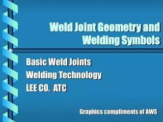
Basic Weld Joints • A welder should understand the type and location of welds needed by reading the welding symbols • A weld joint refers to how the parts are assembled prior to the welding • The item to be joined is base metal or base material
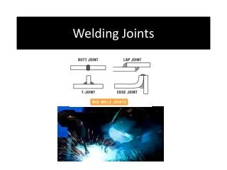
Basic Weld Joints • There are five types of joints used in welding • Butt • Lap • Corner • T-Joint • Edge (American Welding Society)
Butt Joint • Butt joints are used when parts are joined edge-to-edge • Edge preparation refers to how the edges are shaped prior to welding • A groove weld is made by fusing molten filler metal into a butt joint
Butt Joint • The various parts of a groove joint have names • Groove face • Groove angle • Bevel angle • Weld root • Root face
Butt Joint • Various terms are used to describe a completed groove weld • Weld face • Face reinforcement • Weld toe • Root reinforcement • Joint penetration • Weld size
Lap and Corner Joints • A lap joint is formed by two overlapping pieces of base metal • A corner joint is formed by placing two pieces of base metal perpendicular or at an angle to one another • Inside corner joints are welded along the inside of the joint • Outside corner joints are welded along the outside edge of the joint
T- Joint • A T-joint is formed by two pieces of base metal that are at an angle of approximately 90° • The edges may be prepared as a square, bevel-grooved, J-grooved, or flare-bevel-groove joint
Edge Joint and Flange Joint • An edge joint is formed when the surfaces of two pieces are in contact and their edges are even • A flange joint is formed when the edge of one or more pieces is bent to form a flange
Flare-Groove Joint • Flare-groove joints are formed when the flanged edges of one or both pieces are placed together to form a single-flare-bevel or a double-flare-groove
Types of Welds • A weld is a fused joint between two or more pieces of metal or nonmetal • Fillet welds are made at the intersection of a surface and an edge or in a corner where two surfaces meet • A groove weld is made in a groove or gap between two pieces of metal
Types of Welds • A fillet weld is made up of three primary dimensions • Weld size • Effective throat • Leg
Bead Welds and Weld Passes • A weld bead is one weld pass of filler metal that is added to a weld joint • The first weld pass is the root pass • The second weld pass is the filler pass • The final weld pass is the cover pass • Generally, a weld bead should not be thicker than 1/4″
Bead Welds and Weld Passes • Three weld passes are used in this example • The cover pass is a weave bead
Stringer Bead and Weave Bead • A weld bead may be a stringer bead or a weave bead • A stringer bead is used when a standard bead width is acceptable • A weave bead is used to create a wider weld pool • The crescent motion is a popular pattern for a weave bead
Joint Geometry • Joint geometry is defined as the shape and dimensions of a joint, in cross section, prior to welding • Joint geometry is generally determined by a welding engineer or designer • The joint geometry design should provide space for the welder to reach near the bottom of the weld joint
Preparation • The edges of thick metal are prepared for welding • Flame cutting • Gouging • Machining • Preparation allows the weld to penetrate as deep as required
Joint Alignment • The alignment of a joint before welding is very important • A tack weld is a small weld used to hold pieces in alignment • Parts may also be held mechanically using clamps or other devices (Bessey Tools North America)
Penetration • A completed weld joint must be as strong as the base metal • The weld must penetrate deeply into the base metal to be strong • Penetration is the depth of fusion of the weld below the surface
Welding Positions • Welds may be made in various welding positions • Flat welding position • Horizontal welding position • Vertical welding position • Overhead welding position • Welding positions are determined by the positions of the weld axis and weld face
Welding Positions • The weld axis is an imaginary line running lengthwise through the center of a weld
The Welding Symbol • Welding symbols are used on drawings of parts and assemblies that are joined together by welding • A complete welding symbol contains all the information about a welded joint • Dimensions may be in SI Metric units or in US Customary units
Reference Line, Arrowhead, and Tail • The reference line is always drawn as a horizontal line • The arrow may be drawn from either side of the reference line • The tail is used only when necessary to give additional information
Weld Symbols • Weld symbols may be part of the complete welding symbol and indicate the type of weld (American Welding Society)
Arrow Side and Other Side • On the drawing of a weld part, the arrow touches the line to be welded • The side of the metal that the arrow touches is called the arrow side • The opposite surface is called the other side • The arrow side information is always shown below the reference line
Root Opening and Grove Angle • The root opening is the space between the pieces at the bottom, or root, of the joint • Prior to welding, the two pieces will be spaced apart the distance indicated by the root opening • The root opening size appears inside the weld symbol
Contour and Finish Symbols • The shape of contour of the completed weld bead is shown in the welding symbol • Straight or curved line • Placed between the weld symbol and the finish symbol • If the weld is not to remain in an “as welded” condition, a finish symbol is used
Depth of Bevel and Groove Weld Size • The “S” position on the welding symbol • Indicates the depth of the bevel • May indicate the size or strength of welds • May show the size of each leg in a fillet weld • Groove weld size • Is the depth to which the weld penetrates into the base metal • Is given in parentheses in the “E” position on the welding symbol
Depth of Bevel and Groove Weld Size • This illustration shows the depth of the edge shape and groove weld size
Length and Pitch of Weld • Intermittent welding • Short sections of the weld are spaced across the joint • Used when full strength is not needed • The length dimension indicates the length of each weld • The pitch dimension indicates the distance from the center of one weld to the center of the next weld
Length and Pitch of Weld • Intermittent fillet welds may be required on both sides of a joint • With chain intermittent welds, welds begin and end at the same spots • With staggered intermittent welds, the welds are offset • This is shown on the welding symbol by offsetting the fillet weld symbols
Length and Pitch of Weld • This illustration shows a staggered weld • Notice the staggered fillet symbols
Backing Welds and Melt-Through Symbols • Weld joints that require complete penetration may be welded from both sides • A stringer bead or a cover pass may be all that is required • In such cases, a backing weld symbol is used • The melt-through symbol is used when 100% penetration is required on one-side welds
Weld-All-Around and Field Weld Symbols • The weld-all-around symbol indicates that the same type weld joint is to be used on all edges of a box or cylindrical part • When welds are to be made away from the shop, a field weld symbol is used
Multiple Reference Lines • Two or more reference lines may be used when a sequence of operations is to be done • The reference line nearest the arrow indicates the first operation • The reference line furthest from the arrow indicates the last operation
Plug and Slot Welds • A plug weld is a weld made in a hole that is round • A slot weld is a weld made in a hole that is not round • The pitch is the center-to-center distance in a series of plug or slot welds
Spot Welds • A spot weld is a method of joining two or more pieces together with a weld not at the edge of a part • The spot weld symbol is a small circle • Projection welding is another process used to produce spot welds
Spot Welds • The following information is given for a spot weld • Size • Strength • Spacing • Number of welds • Welding process
Seam Welds • A seam weld is another method of joining two or more pieces together • Lap joint • Butt joint • No hole or slot is cut into any parts • The size and strength of the weld are shown to the left of the weld symbol
Review of Welding Symbols • This illustration shows examples of various types of welds in various positions
Electrode Angles • Two terms are used to describe the electrode angle, or position, in relation to the material being welded • Travel angle • Work angle
Travel Angle • The travel angle is measured from a line perpendicular to the weld axis in the plane defined by the weld axis and electrode axis
Forehand welding The welding end of the electrode points forward in the direction of travel The travel angle is called a push angle or push travel angle Travel Angle • Backhand welding • The top of the electrodes leads the welding end of the electrode • The welding arc is pointing back toward the weld bead • The travel angle is called a drag angle or drag travel angle
Work Angle • The work angle is measured from a line perpendicular to the major or nonbutting surface to the plane containing the weld axis and the centerline of the electrode
Commonly Used Angles • For a butt weld, the work angle is usually zero • For a fillet weld, the work angle is often 45° • Drag or push angles usually range from zero to 40° • A large push angle, up to 85°, is used for gouging