Download
1 / 18
261 likes | 818 Views
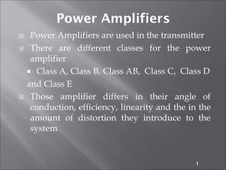
Power Amplifiers Class B, AB,C (CMOS 0.35um,0.18um). Imran Khan. Contents. Introduction Class AB,B,C Results Conclusion. Power Amplifiers. Introduction BFL (choke inductor) has a large value in order to provide an approx. constant current. V dd is fixed for every technology

E N D
Power AmplifiersClass B, AB,C(CMOS 0.35um,0.18um) Imran Khan
Contents • Introduction • Class AB,B,C • Results • Conclusion
Power Amplifiers • Introduction • BFL (choke inductor) has a large value in order to provide an approx. constant current. • Vdd is fixed for every technology • Vin is the input voltage to be amplified • Linearity • Ideal PA is linear but other PAs are linear in certain limits • Efficiency • Normally 30% to 80% • Efficiency=Pout/Pin
Power Amplifiers • Introduction • Gain (voltage, current, power gain) • magnitude of the output signal (Xo) over the magnitude of the input signal (Xi), G= Xo/Xi • Region of Operation • The region of operation of MOSFET is:
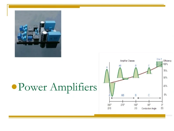
Power Amplifiers • Amplifier Classes • Class A • Efficiency: (10-20)%, theory 50% Linearity: good, Cond. Cycle: 360º • Class B • Efficiency: (35-50)%, theory 78 % Linearity: <A, Cond. Cycle: 180º • Class AB • Efficiency: compromise between A& B Linearity: between A and B, Cond. Cycle: 181º-359º • Class C • Efficiency: (50-60)% max 90% Linearity: worst, Cond. Cycle:<180 Current Flowing The red indicates how much of the drain current is flowing through one wave cycle.
Results- Class B(0.18um) W=375um Vlow=0.39 V
Results- Class AB(0.18um) W=90um Vlow=0.35um
Results- Class C(0.18um) W=950um Vlow=0.1V
Results- Class B(0.35um) W=1250um Vlow=0.1V
Results- Class AB(0.35um) W=350um Vlow=0.6V
Results- Class C(0.35um) W=2.5mm Vlow=0V
Conclusion • Except class A, all PA can be used in Rf systems • PA is the last element in transmission chain therefore requires most attention.