Download
1 / 24
250 likes | 418 Views
FAST KICKERS TESTS AND BELLOWS IMPEDANCE AT DAFNE. Fabio Marcellini, LNF- INFN. LCWS08 & ILC08 Nov 16-20, 2008 University of Illinois, Chicago. PRESENTATION OUTLINE Design of a stripline kicker for beam injection in DAFNE storage rings. HV tests and RF measurements of the kicker.

E N D
FAST KICKERS TESTS AND BELLOWS IMPEDANCE AT DAFNE Fabio Marcellini, LNF- INFN LCWS08 & ILC08 Nov 16-20, 2008 University of Illinois, Chicago
PRESENTATION OUTLINE • Design of a stripline kicker for beam injection in DAFNE storage rings. • HV tests and RF measurements of the kicker. • DAFNE operation with the new kickers. • Realization of a stripline kicker for ILC damping ring. • New DAFNE shielded bellows
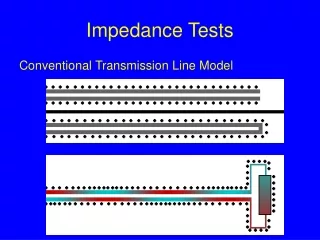
1. DESIGN OF THE NEW DAFNE INJECTION KICKER Input ports Elliptical cross section Strip ceramic supports HV feedthrough Output ports (LOAD) Tapered stripline BEAM
Lk/2 LT • Theelliptical cross section: • Minimizes the discontinuity of the beam pipe cross section between the injection region and the adjacent dipole regions • Increases the deflection efficiency. • The tapered stripline: • Improves the uniformity of transverse deflection as a function of the transverse position • Reduces the contribution of the kicker to the machine impedance • improves the reflection coefficient at high frequency (short pulses) because of smoother transition between feedthrough coax line and stripline. Field flatness by integration 3%
25 kV 45 kV 250 ns 5 ns 2. HV TESTS old pulser (LNF) 50 kV, 50 Ω feedthrough LNF design fast pulser (FID)
2. RF measurements: frequency response Reflection at the input port Special connectors needed to adapt HV connector to RF standards Reflections increase sensibly with the feedthroughs simulations
all ports matched short circuit at each port 50 1000 40 mag mag mag mag real real real real 30 imag imag imag imag 500 20 10 0 0 -10 -20 -500 0 0.5 1 1.5 2 0 0.5 1 1.5 2 f [GHz] f [GHz] 2 ports with short circuits, 2 ports matched (ideal load) 2 ports with short cicuits, 2 ports matched (HV real load) 40 30 30 20 20 ] ] ] ] 10 W W W W [ [ [ [ g g g g 10 n n n n o o o o l l l l Z Z Z Z 0 0 -10 -10 -20 -20 0 0.5 1 1.5 2 -30 f [GHz] 0 0.5 1 1.5 2 f [GHz] 2. RF measurements: longitudinal impedance
3. DAFNE operation with the new kickers New kickers installed in the DANE rings (Nov. 07) Final version of the 45 kV FID pulsers has shown poor reliability. At present only 1 pulser of 4 is good. FID GmbH repaired and updated several times the broken components but a reliable solution has not yet been found. We never had the possibility to operate with the 4 pulsers working together at the same time. We are now running with the old, long pulse system in both the rings. In e+ ring we have succesfully tested injection with a hybrid system connecting both the old pulser and the 45kV fast pulser to each kicker. e- e+ IP
fast pulse kck1 kck2 beam Injection with hybrid system Long and the fast pulses observed in sum at the scope. Taken from 2 striplines of the e+ ring kickers. Different attenuations for signals from the 2 striplines.
DAFNE beam oscillations with fast kick Measured by the horizontal digital feedback system. 100, of 120, stored bunches with kicker pulse centered on bunch 50. bunch distance 2.7 ns.
DAFNE beam oscillations with fast kick rms oscillation amplitude of 100 stored bunches with kicker pulse centered on bunch 50 Same plot with a scale in ns and amplified vertical scale Shows a tail of ~2% above noise level
Experience with FID pulsers First results of operation with FID fast pulsers have been very promising. Routineoperation with 45kV FIDs not allowed because of their very poor reliability. After increasing ß function in the kicker region and changing the beam orbit in the septa, we tried successfully injection with a 24kV, 5ns FID. Pulse shape is the same of the 45kV FID, just lower voltage amplitude. We used this 24 kV FID for lab tests and never had problems up to now. We decided to give up the 45 kV FIDs and try to go on with the 24 kV units. It is possible to have eight 24kV pulsers at the cost of the four 45 kV FIDs. Enough for both the rings. The 24kV FID used for lab HV tests
horizontal fdbk horizontal fdbk e+ ring old pulser old pulser e- ring old pulser old pulser Present situation
horizontal fdbk horizontal fdbk e+ ring old pulser old pulser 20kV fast pulser 20kV fast pulser Short term program (maybe next week) e- ring old pulser old pulser
20kV fast pulser 20kV fast pulser e- / e+ ring 20kV fast pulser 20kV fast pulser Longer term program An additional stripline kck will be installed in e+ ring for the horizontal fdbk. Operation with hybrid solution also possible. More flexible in case of failure of FID pulsers.
ATF PRESENT KICKER 4. A KICKER FOR ATF ATF TAPERED STRIPLINE KICKER Deflecting field along the longitudinal structure axis Blue: straight section stripline Red: tapered stripline Both the structures have been simulated with HFSS
deflecting voltage on the vertical axis deflecting voltage on the horizontal axis Longitudinal coupling impedance Input port reflections Transfer impedances SIMULATION RESULT COMPARISON
Mechanical drawing of the kicker ready. Fabrication starting soon. Kicker is made in stainless steel, 320 mm long. Feedthroughs are commercial available HN-type connectors (CERAMTEC).
5. The new DAFNE bellows • For the DAFNE upgrade, vacuum chamber modifications have concerned: • new interaction regions, • new stripline injection kickers, • all ion clearing electrodes removed in the electron ring. • new bellows • Low impedance design of the new vacuum chamber components Bellows beam coupling impedance obtained by HFSS
Bunch length as a function of bunch current in the electron ring. (left) Bunch charge distribution (@ ~30mA) in the electron ring. (right) Bunch lengthening in: positron ring (left) electron ring (right) few ion clearing electrodes still remaining in the e- ring. coupling impedance has been decreased by about 50% in the positron ring and 70% in the electron ring.
DRAWING OF THE NEW DAFNE BELLOWS Designed for a circular cross section (ø 88 mm) chamber. • The shield is composed of: • 2 cylindrical pipes, welded at the bellows ends, give continuity to the beam pipes except for the gap between them. • 20 Ω shaped, gold-coated, Be-Cu strips, shielding this gap. • A floating thick aluminium ring where the 20 strips are bolted. gold coated strip (a), supporting Al ring (b), bellows assembly (c). THE RF SHIELD CAN FIT DIFFERENT BEAM PIPE CROSS SECTIONS
Due to the high thermal capacity of the supporting ring, the RF shield has a high thermal strength. No specific devices to dissipate the power released by the DAFNE beam on the structure. Tangential magnetic field (current distribution) on the strip surfaces. A cooled version of the bellows has been also considered for possible application on different machines. The bellows convolutions were split in two and an external cooling serpentine is brazed around the supporting ring. See also: EPAC ’08 proceedings TUPP051 and TUPP074
CONCLUSIONS • The new DAFNEinjection kickers, installed one year ago,work welland are very versatile devices.Used with both FID and old DAFNE pulsers and even as a feedback kicker! • Reliability problems of the fast pulse generators by FID remain to be solved, we hope with the 24kV units. • A tapered stripline kicker has been designed for ATF, mechanical drawings already done. Ready to be realized. • A new shielded bellows designed for the DAFNE upgrade as well. It could be easily readapted to different chamber cross sections and a version with cooling is also available. • Together with the new injection kicker, it contributed to lower the machine impedance, as bunch length measurements have shown.