Download
1 / 37
380 likes | 635 Views
Optimization of Semiconductor Superlattice for Spin-Polarized Electron Source. Workshop on Sources of Polarized Electrons and High Brightness Electron Beams. Leonid G. Gerchikov Laboratory of Spin-Polarized Electron Spectroscopy Department of Experimental Physics State Polytechnic University

E N D
Optimization of Semiconductor Superlattice for Spin-Polarized Electron Source Workshop on Sources of Polarized Electrons and High Brightness ElectronBeams Leonid G. Gerchikov Laboratory of Spin-Polarized Electron Spectroscopy Department of Experimental Physics State Polytechnic University St. Petersburg, Russia
Collaborators Department of Experimental Physics, St. Petersburg State Polytechnic University, Russia, Yuri A. Mamaev, Yuri P.Yashin, Vitaly V. Kuz’michev, Dmitry A. Vasiliev, Leonid G. Gerchikov A.F. Ioffe Physicotechnical Institute RAS, Russia, Viktor M. Ustinov, Aleksey E. Zhukov, Vladimir S. Mikhrin, Alexey P. Vasiliev Stanford Linear Accelerator Center, Stanford, CA, USA, James E. Clendenin , Takashi Maruyama Institute of Nuclear Physics, Mainz University, Mainz, Germany,Kurt Aulenbacher, Valeri Yu. Tioukin
OUTLINE • Introduction • Goals of optimization • Problems of optimization • Best photocathodes • Calculations of SL parameters • Energy spectrum • Photoabsorption • Transport • AlInGaAs/AlGaAs SL with strained QW • Optimized design • Results • Summary&Outlook
Goals of optimization High maximal P at large QE
High polarization of electron emission from strained semiconductor SL at the expense of QE Spectra of electron emission:Polarization P and Quantum Efficiency QE SL Al0.2 In0.155 Ga0.65As(5.1nm)/Al0.36Ga0.64As(2.3nm) • Polarization is maximal at photoabsorption threshold where QE is small. • Strain relaxation does not allow to produce thick photocathode with high QE. • Rise of the vacuum level increases P and decreases QE
To get the best P QE • Large valence band splitting > 60 meV • High strain splitting and offsets in valence band • Effective electronic transport along SL axes • High quality SL, uniform layer composition and thickensses • Low doping in SL • Thick working layer • High NEA value • Heavy doped BBR layer
Calculations of SL’s energyspectrum and photoabsorption within 8-band Kane model Miniband spectrum: Photoabsorption coefficient: Polarization:
P&QE of electron emission P0 - initial polarization, Kt , Ke – depolarization factors on stages of transport in SL and emission through BBR, s,t– transport and spin relaxation times in SL. R– reflection from GaAs , B – probability of electron emission through BBR.
Initial electron polarization P0 Polarization spectrum Photoluminescence spectrum Photoabsorption spectrum Energy band spectrum Maximal P0 is limited by: mixture of hh and lh states due to smearing of band edge and broadening of hole spectrum caused by doping and fluctuations of layer composition • Maximal P0 is determined by: • Valence band splitting Ehh-lh= Ehh1 - Elh1 • Broadening of hole spectrum Initial polarization losses amount up to 15% depending on structure quality and design- and Ehh-lh Main optical transitions hh1 – e1lh1 - e1 hh2 - e2lh2 - e2
Initial electron polarization P0 Enlarge Ehh-lh to increase maximal P0 by increase of QW deformation Large strain deformation leads to structural defects and strain relaxation Optimal combination of strain deformation and quantum confinement effect to provide maximal valence band splitting with minimal risk of strain relaxation and good transport properties
Electronic transport in SL Ballistic electron tunneling though SL I=I0T I0 RI0 BBR Tres exp(-b) Tf exp(-2b) Tf << Tres Tunneling probability T = I/I0 Tunneling time =∫ |Ψ(x)|² dx/I
Ballistic transport Tunneling resonances En = E0− ∆E/2Cos(qnd) qn = πn/d(N+1) ∆E – width of e1 miniband N – number of QW in SL Time of resonant tunneling SL= ħ/∆E exp(b) Transport time = ħ/Γexp(2b) Γ << ∆E , >> SL b b b Optimal choice: bf = b/2
Electronic diffusion in SL - electronic density matrix H – effective Hamiltonian of SL in tight binding approximation St{} – collision term including: • collisions within each QW in constant relaxation time , p, approximation • tunneling through last barrier to BBR • optical pumping Kinetic equation Stationary pumping Approximate solution N – number of QW in SL V = E/4 – matrix element of interwell electron transition
Electronic diffusion in SL bulk GaAs D = 40 cm2/s – diffusion coefficient S = 107 cm/s – surface recombination velocity For SL Al0.2In0.2Ga0.6As(5.4nm)/ Al0.4Ga0.6As(2.1nm) D = 12 cm2/s , S = 3*106 cm/s
Pulse response of SL Al0.2In0.16Ga0.64As(3.5nm)/ Al0.28Ga0.72As(4.0nm) 15 periods Time dependence of electron emission D = 16 cm2/s , S = 3.4*106 cm/s * K. Aulenbacher et al, Mainz, 2006
Strained-well SL GaAs BBR Unstrained barrier ab = a0 Strained QW aw > a0 Strained QW aw > a0 Unstrained barrier ab = a0 Buffer Layer a0 - latt. const GaAs Substrate SL Large valence band splitting due to combination of deformation and quantum confinement effects in QW
MBE grown AlInGaAs/AlGaAs strained-well superlattice Eg = 1.536 eV, valence band splittingEhh1 - Elh1 = 87 meV, Maximal polarizationPmax= 92% at QE = 0.85% SPTU & FTI, St.Petersburg
Choice of SL parameters • y - In concentration in QW • x - Al concentration in QW • z - Al concentration in barrier • a – QW width • b – barrier width AlxInyGa1-x-yAs - QW AlxGa1-xAs - Barrier y = 0.2, Ev = 76 meV x = 0.19, Eg = 1.536 eV a = 5.4 nm, Ehh-lh = 87 meV z = 0.4, Uhh = 332 meV, Ulh = 258 meV, Ue = 234 meV, b = 2.1 nm, Ee = 31 meV
SL Al0.19 In0.2 Ga0.61As(5.4nm)/Al0.4Ga0.6As(2.1nm) Pmax= 92%, QE = 0.85%
SL Al0.19 In0.2 Ga0.61As(5.4nm)/Al0.4Ga0.6As(2.1nm) • = 25 meV, P0max = 97% Polarization losses at • photoabsorption – 3% • transport and emission – 5%
Photocathode with DBR Goal: considerable increase of QE at the main polarization maximum and decrease of cathode heatingMethod: Resonance enhancement of photoabsorption in SL integrated into optical resonance cavity Photoabsorption in the working layer: L << 1, - photoabsorbtion coefficient, L - thickness of SL Resonant enhancement by factor 2/(1-(RDBRRGaAs) 1/2)2 Heating is reduced by factor L
Resonant enhancement of QE Accepted for publication at Semiconductors, 2008
Summary & Outlook • Photocathode based on optimized AlInGaAs/AlGaAs strained-well SL demonstrates Pmax= 92% at QE = 0.85%. • Maximal initial photoelectron polarization P0 = 97%. To increase P0 the higher fabrication quality SL is needed. • Optimization of polarization losses and QE on the stage of electron transport and emission needs an additional investigations. • DBR can considerably increase QE and reduce cathode heating.
This work was supported by • Russian Ministry of Education and Science under grant N.P. 2.1.1.2215 in the frames of a program “Development of the High School scientific potential” • Swiss National Science Foundation under grant SNSF IB7420-11111 Thanks for your attention!
Polarization losses Initial electron polarizationP0 for different values of hole spectrum broadening and smearing of absorption edge Polarization losses caused by mixture of hh and lh states due to smearing of band edge and broadening of hole spectrum amount 5-10% depending on structural quality, = 10-30meV. QE spectrumfor different values valence band tails = 10-30meV GaAs0.83P0.17/Al0.1In0.18Ga0.72As (5x4nm)x20
Потери поляризациипри транспорте s – время спиновой релаксации , при T=300K, Na=4*1017cm-3 s = 7*10-11s ext – время выхода электронов из СР в область BBR, ext = d/S + d2/12D, d – ширина СР, S – скорость поверхностной рекомбинациина границе BBR, D – коэффициент диффузии. При T = 300K S = 1/4<v> = 107cm/s. Для тонкого рабочего слоя d = 100nm ext = d/S, ext = 7*10-13s Поляризационные потери ext /s за время транспорта не более1%
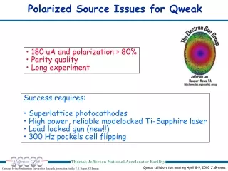
High-Energy physics requirements 90% is better • High electron polarization, P > 80% • High QE for large beam currents • Large electronic current requirement • Light energy limitations: • Surface charge saturation • Heating High QE
Optimization of Photocathode structure • SL structure: layers composition and thickness are chosen to assure • Eg= for P()=Pmax • Ehh-lh > 60meV for high polarization • Ee1 > 40meV for effective electron transport • DBR structure: 20x(AlAs(/4)/ (AlxGa1-xAs(/4)) • Layer thickness l = /4n() for Bragg reflection • x 0.8 for large reflection band width = 2n/n • Fabry-Perot resonance cavity: BBR + SL + buffer layer • Effective thickness = k /2 for QE() = QEmax • Effective thickness of BBR+SL /4
Simulation of resonant photoabsorption • SL’s energy band structure, photoabsorption coefficient, polarization of photoelectrons. Method: kp – method within 8-band Kane model. A.V. Subashiev, L.G. Gerchikov, and A.I. Ipatov. J. Appl. Phys., 96, 1511 (2004). • Distribution of electromagnetic field in resonance cavity, reflectivity, QE. Method: transfer matrixes. M.Born and E.Wolf. Princeples of Optics, Pergamon Press, New York, 1991