Download
1 / 47
470 likes | 580 Views
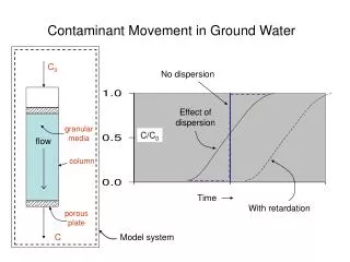
Contaminant Movement in Ground Water. C 0. No dispersion. Effect of dispersion. granular media. C/C 0. flow. column. Time. With retardation. porous plate. C. Model system. Vertical Section View. Point Source of Contaminant. Point Source of Contaminant. groundwater flow direction.

E N D
Contaminant Movement in Ground Water C0 No dispersion Effect ofdispersion granularmedia C/C0 flow column Time With retardation porousplate C Model system
Vertical Section View Point Source of Contaminant Point Source of Contaminant groundwater flow direction Contaminant plume Lines of equal contaminant concentration Plan View
NAPLs: • DNAPLs-Dense Non-Aqueous Phase Liquids • LNAPLs-Light Non-Aqueous Phase Liquids
Subsurface NAPL Free-Phase (Mobile) Residual (Trapped)
Outline • Quantity & Characteristics of Wastewater • Combined Sewer Overflows • Sewer Basics • Sewage Pump Stations • Alternative Collection Systems
How much wastewater do we produce each day? These values are rough estimates only and vary greatly by locale. Wastewater Characteristics
Other Contributions to Wastewater Flows • Infiltration • Older sewer pipe did not have water-tight joints • Sewers follow topography, which means many follow stream-beds or drainage swales where groundwater is high • Since sewers are not under pressure, groundwater can enter in through joints (as well as sewage leak out if ground water is lower than pipe)
Other Contributions to Wastewater Flows • Infiltration rates vary by depth of groundwater, type of pipe joint, and pipe diameter • Infiltration can range from 1,000 gal/day/mile to 100,000 gal/day/mile
How do we quantify water pollution? BOD - Biochemical Oxygen Demand COD - Chemical Oxygen Demand DO - Dissolved Oxygen Levels TKN - Total Kjeldahl Nitrogen Pathogen Levels (Coliforms) NO3-N - Nitrate nitrogen Suspended Solids Aquatic Organisms or lack of (algae, fish, etc.) Heavy Metals Toxicity Wastewater Characteristics
Dissolved Oxygen Dissolved Oxygen (DO) is the amount of oxygen dissolved in a liquid. It can be added to a liquid by aeration or from the natural gas transfer between the air (containing oxygen) and the liquid surface. The amount of DO in a liquid is dependent on the liquid temperature and the salinity. The maximum amount of DO that can be present in a liquid is called the saturated dissolved oxygen level. The DO is used by aquatic organisms. If there is no DO present, the water is considered to be anaerobic. Wastewater Characteristics
Biochemical Oxygen Demand BOD - used to quantify the amount of oxygen used by microorganisms to oxidize dissolved organic and inorganic constituents in a water. BOD5 - the amount of oxygen consumed (in mg/L) over a 5 day period at 20oC (in the dark). BOD5 is a measure of the bioavailability over a 5 day period under controlled conditions. BODu - the maximum amount of oxygen usage by microorganisms over a long period of time. A good measure of maximum bioavailability. Wastewater Characteristics
Biochemical Oxygen Demand Ref: Davis, Cornwell, 1998, Introduction to Environmental Engineering Wastewater Characteristics
Biochemical Oxygen Demand Compound BOD5, mg/L Domestic Wastewater ~ 200 Whole Milk 102,500 Skim Milk 73,000 Coke 67,400 Pepsi 79,500 Tom Collins 66,600 Ethylene glycol 400,000 Wastewater Characteristics
Biochemical Oxygen Demand Carbonaceous BOD (CBOD) - used to quantify the amount of oxygen used by microorganisms to oxidize dissolved organic constituents in a water. Nitrogenous BOD (NBOD) - the amount of oxygen used by microorganisms to oxidize dissolved nitrogen in a water. Wastewater Characteristics
Biochemical Oxygen Demand Ref: Metcalf & Eddy, 1991, Wastewater Engineering Treatment, Disposal and Reuse Wastewater Characteristics
Nitrogen in Wastewater Total Kjeldahl Nitrogen (TKN) - is the sum of organic nitrogen and ammonia nitrogen. Expressed as mg/L as Nitrogen Organic Nitrogen - nitrogen that is complexed with organic constituents (cell tissue, amino acids, proteins, plant tissue, etc.) Ammonia Nitrogen - nitrogen that is in the form of ammonia. Expressed as mg/L NH3-N Nitrite (NO2) nitrogen can be measured directly and is typically expressed as mg/L as NO2-N Nitrate (NO3) nitrogen can be measured directly and is typically expressed as mg/L as NO3-N Wastewater Characteristics
Nitrogen in Wastewater Under aerobic (presence of oxygen), TKN will oxidize to nitrite (NO2) and nitrate (NO3). The oxidation of TKN to nitrate is callednitrification. The reduction of oxidized nitrogen to nitrogen gas (N2) is calleddenitrification. Denitrification can occur under anaerobic (void of oxygen) conditions. Wastewater Characteristics
Other Oxygen Demands Chemical Oxygen Demand (COD) is a measured quantity of oxygen needed to completely oxidize organic and inorganic substances that are present in a water. The COD will oxidize organics/inorganics that would not normally oxidize under natural conditions. The COD is not a measure of the bioavailability or biological activity in a wastewater. COD >> BODu BOD5 Theoretical Oxygen Demand (ThOD) is the theoretical amount of oxygen needed to completely oxidize a substance. Wastewater Characteristics
Solids in Wastewater Total Suspended Solids (TSS) is a measure of the mass of solids that are larger than ~ 1µm in a liquid Volatile Suspended Solids (VSS) is a measure of the mass of TSS that can be burned at 550oC. It is a good measure of biological mass in a water. Fixed Suspended Solids (FSS) is a measure of the mass of TSS that is “inert”. FSS = TSS-VSS Wastewater Characteristics
Other Wastewater Constituents of Concern Phosphorus is a vital nutrient for aquatic plants such as algae. Too much phosphorus may lead to substantial growth of algae in receiving streams and lakes. Aquatic plants get their carbon from CO2 and HCO3 and their energy from sunlight. Heavy Metals: Zinc, Cadmium, Copper, Lead, and etc. that are extremely toxic to aquatic life. Others: pesticides, herbicides, chlorine, and ammonia can be toxic to aquatic life in the receiving stream. Volatile organic compounds enter atmosphere during aeration. Wastewater Characteristics
Wastewater Characteristics Ref: Reynolds, 1996, Unit Operations and Processes in Env. Engineering
Older Systems Have/Had Combined Sewers • Sanitary sewer also collects storm water runoff • Quantity is highly variable and site specific • CSO: Combined Sewer Overflow • Wastewater flows greatly increase during a storm • If capacity of sewer or treatment systems are exceeded, some of the combined waste is discharged with minimal to no treatment
Reducing CSOs • Install separate storm and sanitary sewers • Standard for all new construction • Very expensive for existing systems • Build pipes and treatment plants large enough to handle all flows • Very, very expensive – not feasible • Store combined sewage, then pump to treatment plant when storm ends and flows are back to normal • This option has been selected by many cities, including Seattle and King County
Seattle’s CSO Projects includetunnels and pump stations Milwaukee Deep Tunnels canstore over 400 million gallons ofcombined flowsWastewater is pumped to treatmentplant when flows subside (no storm)
Most Sewers Rely on Gravity Flow • Most sewers are designed to flow by gravity (water flows down-hill) • Includes sewer pipe from home to septic tank or to a municipal collector pipe • Gravity sewers must follow the topography of the land • Where gravity flow is not possible, pumps are used • Individual unit pump • Large municipal lift (pump) station
Hydraulics of Sewers • Most sewers designed to flow at a velocity of 2.0 ft/sec when flowing half-full • Do not want pipe to flow full at peak flows • Do not want pipe flow velocity too low—can’t transport solids • Most designs are complex, but use basic hydraulic equations for computing necessary size and slope
Manning Equation for Pipe Flow • Manning Equation V = velocity (ft/sec) n = coefficient of roughness (dependent upon pipe material/condition) R = hydraulic radius = area/wetted perimeter (ft) S = hydraulic slope (assumed to be slope of pipe) (ft/ft)
Basic Sewer Design • Collector pipes (pipe in street) is minimum 8 inches diameter (to allow cleaning) • Service pipes (home or building to collector is 4 to 6 inches diameter • Gravity sewer pipes have no bends, manholes used to make transitions in direction and pipe size • Pipe sections between manholes are at a constant grade or slope (S)
Typical Manhole Fig 5.1, p 134
Pump Stations • Pump (lift) sewage from low to higher elevation, generally from end of one gravity sewer section to another, higher section • Consist of a wet well and pumps • Wet well forms a place for wastewater to collect and be pumped from
Large Pump Station Source: Metcalf & Eddy, Inc. Wastewater Engineering: Collection, Treatment and Disposal. McGraw-Hill:New York, 1972.
Alternative Collection Systems • Applications • Small community with failing septic systems • New, small developments • Areas where gravity sewers are not feasible • Homes along edge of lake • Areas with unstable soil • Areas with flat terrain • Rolling land with many small elevation changes • High water table • Restricted construction conditions • Rock • Urban development in rural areas • Types of Alternative Systems • Pressure sewers • Vacuum sewers • Small diameter gravity sewers
Pressure Sewers • Each home/building has individual pump • Wastewater pumped to a central treatment location • Pumps “grind” sewage solids
Pressure Systems Can Pump Wastewater Treated by Septic Tank – Used for Homes Previously on Septic Systems
Vacuum Sewers • Wastewater flows by gravity to a central collector well (up to four homes per well) • When well fills a vacuum lines pulls wastewater to a central vacuum tank • Wastewater pumped from central vacuum tank to treatment or a gravity sewer
Vacuum System Components Could also comefrom existingseptic tank
Small Diameter Gravity Sewer Systems • Wastewater flows from home to interceptor (septic) tank where settleable solids and grease are removed • Wastewater flows by gravity to central collector pipe • Central collector pipe can flow full in certain areas • Pipe sizes are typically 4 and 6-inch diameter
Small Diameter Sewer Layout Pipe will flow full, under pressure in these areas
Carnation Treatment System Vacuum collection system Treated wastewater discharged to:1) Uplands (infiltration to groundwater)2) River discharge3) Reuse (irrigation)4) Wetland enhancement/treatment


![C [0]](https://cdn1.slideserve.com/3218926/slide1-dt.jpg)