Download
1 / 35
360 likes | 563 Views
3D Hidden Surface Removal. 2001.2.28 김 성 남. Contents. Goal Motivation Approaches - back face detection - depth buffer - A-buffer - Scan line - Depth sorting - BSP-tree - Area subdivision - Ray casting Conclusion. Goal.

E N D
3D Hidden Surface Removal 2001.2.28 김 성 남
Contents • Goal • Motivation • Approaches- back face detection- depth buffer- A-buffer- Scan line- Depth sorting- BSP-tree- Area subdivision- Ray casting • Conclusion
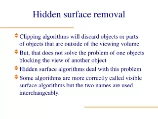
Goal • A major consideration is identifying those parts of a scene that are visible from a chosen view position. • Represent realistic 3D display • Visual-surface detection methods≈ hidden-surface elimination methods
Motivation (1/4) • Surfaces may be various of situations according to view positions.- surfaces may be back-facing
Motivation (2/4) • Surface may be occluding
Motivation (3/4) • Surfaces may be overlapping
Motivation (4/4) • Surfaces may be intersecting
Approaches • Back-face detection • Depth buffer • A-buffer • Scan line • Depth sorting • BSP-tree • Area subdivision • Ray casting
Classification • Object–space methods- Viewer의 가시선상에서object가 보이는지,안보이는지를 직접 결정- wire frame display에서line display시 사용 • Image-space methods- using most methods- projection plane상의 각pixel position에point에 따라visibility결정
Back-face detection (1/2) • Fast & simple object-space method • Be based on Inside-outside test- decide on the back face P(x,y,z) on the polygon Ax + By + Cz + D < 0 inside back face V • N > 0 back faceV : Viewing direction vector(eye,camera) N : Normal vector to a polygon surface
Back-face detection (2/2) V를 다음과 같이Vz축에 평행하게projection coordinates로 convert한다면 Vy Vx V = (0,0,Vz) Vz V V • N = VzC ( C : variable) C의 기호(+ or -)에 따라back face 결정C ≤ 0 N V viewer
Vy Vx S3 S2 S1 Vz Depth-Buffer Method (1/3) • Image-space method • Compare surface depths at each pixelposition on the projection plane. • Z-buffer method
Depth-Buffer Method (2/3) • Step- initialize the depth & refresh buffer depth(x,y) = 0, refresh(x,y) = Ibackground- compare depth values to previously stored values in depth buffer • Calculate the depth z for each (x,y) position on the polygon • if z > depth(x,y), then set depth(x,y) = z, refresh(x,y) = Isurf(x,y)
Depth-Buffer Method (3/3) • Comments- requires lots of memory a system with resolution 1024 by 1024 = 1024 x 1024 x 24bits- subject to aliasing(A-buffer)- commonly implemented in hardware
A-Buffer Method (1/3) • Extension of the depth-buffer method • Antialiased,Area-averaged,Accumulation-buffer method by Lucasfilm • For implementation in the surface rendering system- REYES(Renders Everything You Ever Saw) • Viewing for more than one surface • Antialiasing
A-Buffer Method (2/3) • A-Buffer has two fields- depth field : store +,- real number- intensity field • Using Linked list - d > 0 : single surface overlap - d < 0 : multiple surface overlap Surf1 Surf2 d > 0 I • • d < 0 • Depthfield Intensityfield Depthfield Intensityfield
A-Buffer Method (3/3) • Included data in the linked list- RGB intensity components- Opacity parameter(present of transparency)- Depth- Persent of area coverage- surface identifier- other surface-rendering parameters- pointer to next surface foreground transparent surface background opaque surface
Scan-Line Method (1/2) • Image-space method • Extension of the scan line algorithm • Using Edge tables, polygon tables • Set up an active list of edges cross the current scan line • Define a flag for each surface (on or off)- to indicate whether inside or outside • Take advantage of Coherence along scan lines • Commonly implemented in software
C G F Scan line 1 S1 S2 Scan line 2 Scan line 3 D E A B Scan-Line Method (2/2) • Scan line 1 : no depth calculations • Scan line 2 : depth calculations • Scan line 3 : no depth calculations- take advantage of coherence
Depth Sorting Method (1/7) • Both image-space and object-space method- sorting operation : both- scan conversion : image-space method • Painter’s algorithm : oil painting • Sort surfaces in order of decreasing depth • No depth overlap - Scan convert surfaces in order, starting with the surface of greatest depth • Depth overlap- need to additional reordering process
Depth Sorting Method (3/7) • Overlap test1.Bounding rectangles in the xy plane for the two surfaces do not overlap.2.Surface S is completely behind the overlap -ping surface relative to the view position3.Overlapping surface is completely in front of S relative to the view position4.The projections of the two surfaces onto the view plane do not overlap one of these test is true no reordering
S S’ Vx Xmin Xmax X’min X’max Vz Depth Sorting Method (4/7) 1. bounding rectangles in the xy plane for the two surfaces do not overlap
Depth Sorting Method (5/7) 2.Surface S is completely behind the overlap-ping surface relative to the view position 3.Overlapping surface is completely in frontof S relative to the view position S S S’ S’ Vx Vx Vz Vz Test2 is not true Test2,3 are true
Depth Sorting Method (6/7) 4.The projections of the two surfaces onto the view plane do not overlap
Depth Sorting Method (7/7) • When 4 tests failed,interchange surfaces in the sorted list S S S’ S’ S’’ Vx Vx Vz Vz In sorted list S’,S S,S’ In sorted list S,S’,S” S’,S”,S
BSP-Tree Method (1/2) • A kind of Depth-sorting Method • Be useful when the view reference pointchanges,but the objects are fixed position • Painting in the order back to front • Commonly implemented in hardware
BSP-Tree Method (2/2) P2 P1 back C front P1 front front back back P2 P2 D A front back front back A C B D B Painting order D → B → C → A
Area-Subdivision Method (1/4) • Image-space method- object-space method : depth ordering • Start with total view → determine whether subdivision or not →subdivision → until a single surface or the size of a single pixel • Similar to quad tree
Area-Subdivision Method (2/4) surface Boundary area • If one of conditions is true, no subdivision1. All surfaces are outside2. Only one surface intersects in the area3. One surface occludes other surfaces within area Surrounding surface Overlapping surface inside surface outside surface
Area-Subdivision Method (3/4) • All surfaces are outside- check the bounding rectangles of all surfaces against the area boundaries • Only one surface intersects in the area- bounding rectangles can be used as initial check- no intersection → inside intersection → need to additional check whether overlap,outside,surrounding
Area-Subdivision Method (4/4) • One surface occludes other surfaceswithin area - using 4 vertices method the minimum depth of all other surface within the area maximum depth of surrounding surface > Zmax(surroundingsurface) Vx Vz Area
Ray Casting Method (1/2) • Cast ray from viewpoint through each pixelto find front-most surface
Ray Casting Method (2/2) • Light-ray paths backward from the pixelsthrough the scene • More effective detection method- Curved surface, particularly spheres • a variation on the depth buffer method • Conceptually simple, but not generally used
Summary • Hidden Surface Removal Algorithm- Back-face detection- Depth buffer- A-buffer- Scan line- Depth sorting- BSP-tree- Area subdivision- Ray casting