Download
1 / 28
290 likes | 1.13k Views
Microstrip Transmission Line Design with Left-Handed Material Properties. Final Presentation ECE 445 Group 39 Xu Chen · Brian Boerman. Introduction. Project based on research by C. Caloz and T. Itoh at UCLA

E N D
Microstrip Transmission Line Design with Left-Handed Material Properties Final Presentation ECE 445 Group 39 Xu Chen · Brian Boerman
Introduction • Project based on research by C. Caloz and T. Itoh at UCLA • “Transmission Line Approach of Left-Handed (LH) Materials and Microstrip Implementation of an Artificial LH Transmission Line”, May 2004, IEEE Transactions on Antennas and Propagation
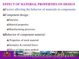
Metamaterials • A class of composites that exhibit exceptional properties not readily found in nature
Left-Handed Materials • A type of metamaterial with simultaneous negative permittivity and permeability, and a negative index of refraction • First proposed in 1968 by Veselago • Left-handed refers to the Left Hand Triad (E, H, k) obtained from Maxwell equations • Science magazine listed LH materials as one of the ten greatest scientific breakthroughs in 2003
Characteristics of the Line • Characteristic Impedance • For regular transmission lines, Where Z is the impedance of the series items and Y is the admittance of the parallel items
Characteristics of the Line • Wavenumber
Characteristics of the Line • Velocity of Propagation
Objective • To design a microstrip transmission line that would exhibit properties of Left-Handed (LH) materials • To simulate the design and prove the LH properties • To test the physical board and verify the results
Original Design • Design for 2 GHz • Calculations show: • Series capacitance = 12.8 pF • Shunt inductance = 32 nH • 5 capacitor/inductor sections • Assume ideal transmission lines • Transmission lines are designed to have characteristics impedance of 50
Design Principles • In order to design the dual of an ordinary transmission line, shunt inductance and series capacitance must be used • This is achieved through the use of interdigitated capacitors and through loop inductors • Design is done in Sonnet
Design Process • To achieve desired values of C and L, dimensions of the interdigitated capacitor and through loop inductor are varied • Since the elements cannot be measured up-close at high frequencies, two segments of transmission lines are added to the sides • S-parameters of the whole system (line - L/C - line) as well as the standalone line is generated using Sonnet • S-parameters of the inductor or capacitor can be extracted through de-embedding
ABCD Parameters • ABCD parameters were used for de–embedding of components • Utilized because ABCD parameters can be cascaded
Capacitor testing • Capacitor tested using B element of de-embedded ABCD parameters • The B element of a series element is equal to the impedance of that element • “B”
Inductor testing • Inductor tested using the C element of the de-embedded parameters • The C element is equal to the admittance of a parallel element • “C” =
Challenges • Specifications set forth by the circuit board manufacturer minimum spacing, minimum line width, through hole diameter • Capacitor value fell short of 12.8 pF goal • Original capacitor design is not good because parasitic inductance takes over at high frequencies - resonance point
Review of Design • Necessary to have 50 ohm characteristic impedance, so or
Review of Design • Cutoff frequency • High pass network, so cutoff frequency must be below some minimum value to have good operation over specified range
New design • Capacitor value of 2.662pF • Inductor value of 6.286nH
New Design • Characteristic Impedance
Applications • New types of beam steerers, modulators, band-pass filters, superlenses, microwave components, and antennas
Microwave Applications • Dual-band Branch-line Coupler • Zeroth Order Resonator Antenna • Backfire-to-Endfire Leaky-Wave Antenna • Planar Negative Refractive Index Lens
Thanks To • Professor Cangellaris • Adam Gustafson • Professor Swenson • Jim Wehmer


![[PDF] DOWNLOAD FREE Left handed notebook: Left handed notebook wide ruled c](https://cdn7.slideserve.com/12443003/left-handed-notebook-left-handed-notebook-wide-dt.jpg)