Download
1 / 29
290 likes | 354 Views
Rational Rose 2000 Class Diagrams. Module Objectives. Define analysis classes. (already done) Define view of participating classes (VOPC) class diagram. Use Rational Rose to add a class and create a VOPC diagram. Run a script auto generate VOPC diagram.

E N D
Module Objectives • Define analysis classes. (already done) • Define view of participating classes (VOPC) class diagram. • Use Rational Rose to add a class and create a VOPC diagram. • Run a script auto generate VOPC diagram. • Run reports to show class instances and usage.
Where Are We? The Analysis and Design Workflow Classes and class diagram are initially identified and created respectively during the elaboration phase of this workflow. Some classes may be identified as late as the construction phase for use cases that were not previously analyzed.
Where Are We? – Use Case Analysis Classes and class diagrams are identified and refined during the activities outlined ahead. Use case analysis Identify classes that perform a use case’s flow of events. (analysis classes) Distribute use case behavior to those classes, using use case realizations. Identify the responsibilities, attributes, and associations of the classes. Input artifacts Glossary • Use case model Supplementary specifications • Use case realizations Use case modeling guidelines • Software architecture document
Where are we? – We will be doing: - Use Case Design • Use case design Replace analysis classes with design subsystems and classes. • Refine requirements on the operations of subsystems and/or their interfaces. • Input artifacts Supplementary specifications Design subsystems Use cases Interfaces Use case realizations Design classes
Then: Subsystem Design Subsystem design Define realizations between the subsystem's interfaces and contained classes Document internal structure of the subsystem. Define realizations between the subsystem’s interfaces and contained classes Determine dependencies on other subsystems. Input artifacts Use case realizations Design subsystem with interface definitions Design guidelines
Then Class Design Class design Ensures that the class provides the behavior the use case realizations need Ensures that sufficient information is provided to unambiguously implement the class Handles non-functional requirements related to the class. Incorporates the design mechanisms used by the class. Ensures that the class provides the behavior the use case realizations need Input artifacts Supplementary specifications Use cases Design Guidelines Use case realizations Design classes Design model
Key Concepts • Analysis classes • Represent the prototypical classes of the system. • Stereotyped as boundary, control, and entity. • Boundary classes used to model interactions between a system’s surroundings and its inner workings. This class models parts of the system that depend on its surroundings, such as printer interfaces. • Control classes are used to model control behavior specific to one or a few use cases. Models parts of the system that are independent of the system’s surroundings. • Entity – used to model information and associated Behavior that must be stored. Entities represent the key concepts of the system. As we move to class design, analysis classes may be refined into design classes or drop out entirely.
Key Concepts: Analysis vs Design Classes Analysis classes represent functional requirements of the problem domain. Design classes represent the non functional requirements of the solution domain. Again, we move from what the system should do to how the system will do it.
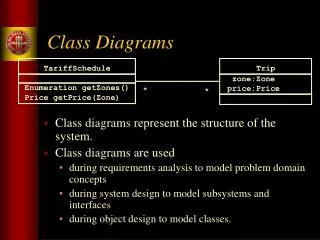
Key Concepts • Class diagram • VOPC (classes only shown here) Class Diagrams: . Show a set of classes, interfaces, and collaborations and relationships . Modeled to show static view (logical view) of system; . Primarily supports functional requirements of the system View of Participating Classes: . A class diagram that shows a use case realization’s participating classes and their relationships. Shows all classes whose instances collaborate to perform use case. . Ensures consistency in use case implementation across subsystem boundaries.
Key Concepts • Multiplicity • Role names • Aggregation Multiplicity: Defines number of objects that participate (and are linked) in relationship; Aggregation: Specialized form of association where a whole is related to its part(s). Is known as a ‘part of’ or containment relationship. Has open diamond next to class denoting the aggregate (whole). Role Names: Can be used instead of association names; Is a noun indicating purpose or capacity wherein one class associates with another; Placed on association near class it modifies; Can be placed on one or both ends of association line. (Not necessary to use both.)
Build Classes: • Objectives • Add a class. • Create VOPC class diagram. • Create a VOPC diagram from a script. • Run a report to show class instances • Run a report to show usage.
Stereotype indicated Documentation added Entity class added to browser Add a Class In Logical View, right click Design Model; New; Class; type Student (namespace warning) Right click Student; Open Specification; In stereotype list: entity; In Documentation field type: A person enrolled in classes at the university; Analysis mechanism: persistency, security. Click OK. Notice what happens to the class in the browser; Keep model open…
Attributes added to class specification Operations added to class specification Attribute added Operation added Add a Class (continuing) Add Attributes: Right click Student; New; type Address over Name Repeat steps for additional attributes. When done adding attributes, Right click Student class; Open Specs; Click Attributes to view your additions. Add Operations: Right click Student; New; Click operation, then type: //get tuition over opname. Continue to add additional operations. At end, Right click Student class, Open Specs, click Operations to view additions.
VOPC class diagram added to browser Create a VOPC Class Diagram Add the class diagram In the browser, expand Logical View, Design Model, and expand Use Case Realizations. Expand Use Case Realizations – Register for Courses Right click Register for Courses. New; click Class Diagram (note class diagram symbol.) Type Register for Courses - Basic Flow (VOPC) over NewDiagram. Double-click on Register for Courses - Basic Flow (VOPC). The class diagram window is displayed.
Create a VOPC Class Diagram Classes added to diagram Bird’s eye view Add participating classes In the browser, drag the RegisterForCoursesForm boundary class onto the diagram. Repeat step 1 for the remaining classes. Arrange the diagram. Keep model open For large diagrams like this one, use the bird’s eye view. Click the small hand in the lower right corner of diagram. Now scroll freely around the diagram. To show class attributes and/or operations, right-click the class. Click Options; then click Show All Attributions and/or Show All Operations.
Unidirectional associations added Aggregation Bi-directional associations Generalization Create a VOPC Class Diagram - more Add associations and relationships Make sure all associations and relationships are on your toolbar. (IF not, add them) Add all associations and relationships as appropriate. Note two bi-directional associations between Schedule & CourseOffering classes. Bi-directional associations allow information to flow in both directions. Classes can have more than one message passing between them. You can apply the “by value” adornment to an aggregate relationship between two classes to show that an instance of one class allocates storage for and has within it an instance of the other class.
Multiplicity added Role name added Create a VOPC Class Diagram - more… Add role names Double-click the association between the RegistrationController and Student classes.The Association Specification is displayed. In the Role A field, type registrant. Click OK. Note that you’ve used Role A because registrant modifies the Student class. Repeat steps 1 and 2 for the role name modifying the Schedule class.
Multiplicity added Role name added Create a VOPC Class Diagram - more… Add multiplicity Double-click the association between the RegistrationController & CourseCatalogSystem The Association Specification is displayed. Click the Role A Detail tab. In the Multiplicity list, click 1. Click the Role B Detail tab. In the Multiplicity list, click 0..n. Click OK. . Common multiplicity indicators • 1 Exactly one 0..1 Zero or one • 0..* Zero or more 5.. 8 Specific range (5, 6, 7, or 8) • 1..* One or more 4..7,9 Specific range (4, 5, 6, 7, or 9)
Green start arrow is pressed VOPC diagram name added Run Script to Generate VOPC Diagram Run a script to add VOPC diagram Expand Logical View; Expand Design Model; expand Use Case Realizations; Double-click Traceabilities. In the diagram window, click the Register for Course use case realization. On the Tools menu, click Open Script. Open C:\RoseSolutions\Scripts, then double-click VOPC.ebs. .On the toolbar, click the green start arrow to run script. The Class Diagram window is displayed. Type Register For Courses - Basic Flow (VOPC), then click OK. In the browser, expand Use Case Realization - Register for Courses VOPC diagram. You may move classes and clean up diagram.
Show Instances selected Class selected List of diagrams is displayed Show Instances If your model is large, you may want list of all the interaction diagrams on which a class appears. The Show Instances report is an easy way to view this information. Run the Show Instances report Browser; expand the Logical View; expand Design Model; expand Use Case Realizations. Expand Use Case Realizations - Register for Courses, then expand Register for Courses. Double-click the Register for Courses - Basic Flow (VOPC) class diagram. Click a class. On the Report menu, click Show Instances. The Show Instances window is displayed. Browse through the window to view the interaction diagrams on which the class appears. Now, let’s run another report. Leave your diagram open.
Show Usage selected Class selected List of locations is displayed Show Usage Again, if your model is large, you may want a list of where a selected element is used in the model. Note that this report can be run for actors, use cases, use case realizations,…. Run the Show Usage report 1. Click a class. 2.On the Report menu, click Show Usage. The Show Usage window is displayed. 3.Browse through the window to view where the selected class is used in the model. Pause a moment and review our preferred practices.
Preferred Practices • Class Design • Relationships • Generalization • Use for “is a” relationships. • Don’t use simply to make definitions visible, except for <<interface>> classes. • Aggregation • Use for “part of” relationships. • Don’t use in place of dependency between loosely coupled classes. • Navigability • Reduce bi-directional to unidirectional relationships, where possible.
Preferred Practices • Relationships • Names • Name roles and/or name associations when meaningful for the associations. • You don’t need to name everything. • Name associations or roles, not both. • Know there are different choices for different associations. • Multiplicity (cardinality) • Explicitly, specify multiplicity.
Preferred Practices • Completion Specification • Descriptions • On creation, enter brief descriptions for all elements—class, attribute, and operation. • Use for data dictionary. • Include to convey a clear purpose to multiple readers. • Attribute specifications during design • A type • A default value, when possible • Private access (rarely need public access)
Preferred Practices • Completion Specification • Operation specifications during design • Return type • Parameter definitions • Parameter default values • Limit use of public access Operations The primary mechanism to access attributes is through operations. Rose defaults all operations to public access. During analysis, this is appropriate. During design, however, limit the use of public access to only where it is needed. The more limited the public interface, the more freedom there is to change the implementation.
Preferred Practices • Dependencies • Create dependency relationships for • Attributes whose types is a class use association (field visibility. • Operations whose return type is a class use dependency (parameter visibility). • Operations whose parameters are classes’ uses dependencies (parameter visibility). • Operations whose implementation creates objects of class uses dependencies (local visibility).
Preferred Practices • VOPC class diagram • Create diagram in its use case realization package. • Create at least one diagram for each use case realization. • Show classes and relationships needed to support interactions.