High Performance Triplex Adder using CNTFET
Carbon Nanotubes Field Effect Transistors CNTFETs is used to implement a two new design of triplex half adder. conventional binary logic has a capable alternate called triplex logic, since it is possible to accomplish uncomplicatedness and energy efficiency in modern digital design due to shortened circuit overhead such as interconnect and chip area. Triplex decoders and binary logic gates are used to present two novel half adders. To obtain power, delay and power delay product the circuits are simulated using HSPICE . Recently reported designs are compared with these circuits. These triplex adders show delay and power advantage up to 40 and 39 with less transistor count. So, using these half adders in complex arithmetic circuits will be advantageous. G. Naveen Balaji | S. Chenthur Pandian | D. Rajesh "High Performance Triplex Adder using CNTFET" Published in International Journal of Trend in Scientific Research and Development (ijtsrd), ISSN: 2456-6470, Volume-1 | Issue-5 , August 2017, URL: https://www.ijtsrd.com/papers/ijtsrd2300.pdf Paper URL: http://www.ijtsrd.com/engineering/electronics-and-communication-engineering/2300/high-performance-triplex-adder-using-cntfet/g-naveen-balaji<br>

High Performance Triplex Adder using CNTFET
E N D
Presentation Transcript
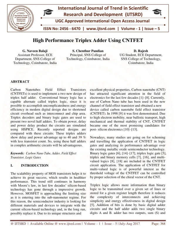
International Journal of Trend in Scientific Research and Development (IJTSRD) UGC Approved International Open Access Journal ISSN No: 2456 - 6470 | www.ijtsrd.com | Volume - 1 | Issue – 5 High Performance Triplex Adder Using CNTFET G. Naveen Balaji Assistant Professor, ECE Department, SNS College of Technology, Coimbatore, India S. Chenthur Pandian Principal, SNS College of Technology, Coimbatore, India D. Rajesh UG Student, ECE Department, SNS College of Technology, Coimbatore, India excellent physical properties, Carbon nanotube (CNT) has attracted significant attention in the field of electronics for the last few decades [1]–[8]. Currently, use of Carbon Nano tube has been used in the new channel of field effect transistor and obtained a new device called carbon nanotube field effect transistor (CNTFET). In 1998 [9] it was first demonstrated. Due to high electron mobility, near ballistic transport, high mechanical and thermal stability of CNT, CNTFET became one of the most promising candidates for post- silicon electronics [10]–[13]. Nowadays, many studies are going on for scheming and travelling the application of CNTFET in logic gates and analyzing its performance advantage over the existing metallic oxide semiconductor technology. Binary logic gates [6], [14]–[17], triplex logic gate [5], triplex and binary memory cells [7], [16], and multi- valued logics [8], [18] are included in the CNTFET circuit application. The application of CNTFET for multi-valued logic is of powerful interest as the threshold voltage of the CNTFET can be controlled by proper selection of the chiral vector of the CNT. Triplex logic allows more information than binary logic to be transmitted over a given set of lines or stored for a given register length therefore it reduces the complexity of interconnects and achieving simplicity and energy effectiveness in digital design [5]. Addition of bits is done by basic digital adder circuits and the half adder adds two single binary digits A and B. adder has two outputs, sum (S) and ABSTRACT Carbon (CNTFETs) is used to implement a two new design of triplex half adder. Conventional binary logic has a capable alternate called triplex logic, since it is possible to accomplish uncomplicatedness and energy efficiency in modern digital design due to shortened circuit overhead such as interconnect and chip area. Triplex decoders and binary logic gates are used to present two novel half adders. To obtain power, delay and power delay product the circuits are simulated using HSPICE. Recently reported designs are compared with these circuits. These triplex adders show delay and power advantage up to 40 and 39 % with less transistor count. So, using these half adders in complex arithmetic circuits will be advantageous. Nanotubes Field Effect Transistors Keywords: Carbon Nano Tube, Adder, Field Effect Transistor, Logic Gates I. INTRODUCTION The scalability property of MOS transistors helps it to achieve its great success, which results in healthier performance. This trend still continues in harmony with Moore’s law, in last few decades’ silicon-based technology has gone through a impressive growth. However, MOSFET is approaching the limiting size as it is entering into the sub-nanometer regime. For this reason, the semiconductor industry is looking for different materials and devices to integrate with the current silicon-based technology and, in the long run, possibly replace it. Due to its unique structures and @ IJTSRD | Available Online @ www.ijtsrd.com | Volume – 1 | Issue – 5 | July-Aug 2017 Page: 368
International Journal of Trend in Scientific Research and Development (IJTSRD) ISSN: 2456-6470 Triplex Logic (Three-valued logic): Triplex logic functions include a third value in addition to the binary logic. In this 0, 1, and 2 are used in triplex logic to symbolize the triplex values false, undefined, and true, respectively. Any n variable {X1, . . . ,Xn }triplex function f(X) is called as a logic function plotting {0, 1, 2}nto {0, 1, 2}, where X = {X1, . . . , Xn} [5]. Advantages of triplex logic are: 1. The number of required computational steps gets reduced. n bit binary number is represented by log32n bits Number of digits required to symbolize in triplex is log3 2 times less than required in binary. Due to reduced complexity of interconnects and chip area it is simple and energy efficient. Interconnect and pin-out encountered by the binary integrated circuits are eliminated. Therefore, triplex logic needs lesser number of bits, memory and number of chip pins. For example, decimal number 8, in triplex it can be represented as (22)3, where in binary it can be represented as (1000)2 carry (C). The carry signal denotes an overflow into the next digit of a multi-digit addition. They disperse lots of energy, increase response time and cause coupling effects by adding more capacitance, resistance, inductance to a circuit. Multiple-valued logic (MVL) is an alternative solution to interconnect complexity and growing power dissipated by wires. Wires inside the chip are reduced. Outside a chip dramatically as more complex designs require a large number of wires for connecting circuit components [5]. In the new work two new circuits are proposed for triplex half adder circuit to have better act. The reported circuits give delay and power advantages up to 40% and 39 % with less transistor count in comparison to other work. Basic of multiple value logics and more definitely triplex logic is discussed in section II. The CNTFET’s suitability for triplex logic are discussed in section III. Some basic logic gates and the previously best reported half adders are discussed in section IV. Our proposed circuits, their implementation and comparisons with other reported circuits are analyzed in section V. The final concluding remark is given in section VI. 2. 3. 4. problems that are 5. III. CNTFETANDITSSUITABILITYFOR MVL The structure of a CNTFET is as same as conventional MOSFET in which semiconducting channel layer is built with semiconducting CNT single layer. The suitability of CNTFET for the application in multi-valued logic lies in the fact that the threshold voltage of the CNTFET can be modified slightly and controlled by proper selection of the chiral vector of the CNT. This is due to the threshold voltage for a CNTFET depends on the band gap of the CNT, Band gap of CNT depends on the orientation of the graphene sheet to obtain the CNT. If (n, m) denotes the chiral vector, which be influenced by on the direction of rolling of the graphene sheet, of the CNT which is used in the channel region of the CNTFET then the diameter of the CNT is given as: dCNT=a/rπ(n2+m2+nm)1/2 where r|a1|=|a2|=1.42*square root of 3=2.46 amstrong Here a1 and a2 are the primitive lattice vectors of graphene from which the CNT is obtained II. MULTIPLEVALUEDLOGICREVIEW Multiple-valued logic (MVL) uses more than two values in contrast to the binary digital computation and it is performed using only two possible values (0 or 1, true or false). Nowadays, multiple-valued logic, such as triplex logic (or three-valued logic), has attracted considerable interests due to its budding advantages over binary logic for crafty digital systems. Requirement of interconnections and reduction of chip area, high bandwidth parallel, serial data transfer, high potential for increasing computational speed and reducing switching activity and employment of many arithmetic and logic functions in a single chip are some of the benefits of MVL. less memory, less Among many Multi valued logic systems, triplex logic (also known as three-valued logic) has been of more interest than any other due to its simplicity and efficiency. In this work we have focused on triplex logic which is Multi valued logic with three levels. @ IJTSRD | Available Online @ www.ijtsrd.com | Volume – 1 | Issue – 5 | July-Aug 2017 Page: 369
International Journal of Trend in Scientific Research and Development (IJTSRD) ISSN: 2456-6470 Fig: 1 Structure of CNTFET various logic gates like inverter, NAND, NOR, AND, OR are reported in literature [5]. TABLE 1: LOGIC SYMBOL AND VOLTAGE LEVEL USED IN TRIPLEX LOGIC Logic Value 0 1 As shown in Fig.1, channel region is created by placing undoped CNT under the gate and heavily doped CNT segments are placed between the gate and the source/drain to allow for a low series resistance in the ON- state. While the gate potential increased, the device is electro statically turned on or off via the gate and the threshold voltage of the intrinsic CNT channel can be approximated to the first order as the half band gap that is an inverse function of the diameter and is given as: aVu Voltage Level 0 (1/2)Vdd 2 Vdd Vth = In triplex system consist of three types of inverters: negative triplex inverter (NTI), standard triplex inverter (STI) and positive triplex inverter (PTI) [5]. Three inverters symbols and truth tables are given below in Fig. 2 and Table-II. 43ed€NT Here Vu = 3.033 eV is the carbon π –π bond energy in the tight binding model, e is known as the unit electron charge, d€NT is the diameter of the CNT plotted in the channel. By this we know clearly that the threshold voltage of a CNTFET varies inversely with the diameter of the CNT and it can be modified to a required value by choosing proper chiral vector. For this major advantage of CNTFET to be used for triplex logic. (a) (b) (c) Fig 2: Symbols of (a) NTI (b) STI and (c) PTI Output for STI 0 2 1 1 2 0 IV. TRIPLEXLOGICGATESANDHALF ADDER Output for PTI 2 2 0 Output for NTI 2 0 0 Input Basics of triplex logic and its representation in terms of voltage level is discussed in this section. And the best recent reported half adder circuits from literature are used. Based on this circuit, improved two half adder circuits are offered in next section. In triplex logic three symbols used are 0, 1 and 2. The voltage level used in terms of Vdd to represent each symbol is given in Table 1. Using this triplex logic TABLE 2: TRUTH TABLE FOR STI, PTI AND NTI @ IJTSRD | Available Online @ www.ijtsrd.com | Volume – 1 | Issue – 5 | July-Aug 2017 Page: 370
International Journal of Trend in Scientific Research and Development (IJTSRD) ISSN: 2456-6470 For understanding other logic gates, we will assume Xi, Xj are two inputs given as Xi, Xj= {0, 1, 2}. After that the basic logical operations in triplex logic can be understood as follows: OR : Xi + Xj= max(Xi, Xj) AND : Xi . Xj= min (Xi, Xj) NAND : ¯X¯ı¯.¯X¯ȷ = m¯ ¯a¯x¯(¯X¯ı¯.¯X¯ȷ¯) NOR : ¯X¯ı¯+¯ ¯X¯ȷ = m¯ ¯ı¯n¯ (¯X¯ı¯+¯ ¯X¯ȷ¯) The various symbols used for these triplex logic gates are shown in Fig. 3. Fig. 3: Symbols used for triplex logic gates Fig 5: Tenary half adder replacing portion of triplex logic by binary logic gates A B 0 0 0 1 0 2 1 0 1 1 1 2 2 0 2 1 2 2 TABLE 3: TRUTH TABLE OF HALF ADDER Designed and reported by Lin et.al [5]. In this design the triplex logic gates are replaced with binary logic gated as shown in Fig. 5. This replacement of triplex logic gates by binary logic gates has reduced the transistor count and hence improved performance. A triplex decoder consists of a one-input, three-output combinational circuit. It generates unary functions for an input x. The response of the triplex decoder to the input x is given by Xk = {20 if x if x = k≠ k Where both x and k can take any values 0, 1 and 2. Using this type of triplex logic gates, a half adder is designed and shown in Fig. 4 [19]. Table III is the truth table for this triplex adder. An improved version of adder is in our proposed circuit, the AND-OR circuit is replaced by NAND –NOR circuit as shown in Fig 6. due to this the number of transistor is reducing. Again the 3 AND and 1 OR gate combination of Fig. 5 is replaced by transistor level circuit as shown in Fig. 7. This also reduced the number of transistors to 94. Sum Carry 0 1 2 1 2 0 2 0 1 0 0 0 0 0 1 0 1 1 Fig.4 Triplex half adder V.PROPOSEDTRIPLEXHALFADDER The triplex half adder circuit given in Fig 5 uses binary logic gates. This circuit is implemented using AND –OR logic gates. @ IJTSRD | Available Online @ www.ijtsrd.com | Volume – 1 | Issue – 5 | July-Aug 2017 Page: 371
International Journal of Trend in Scientific Research and Development (IJTSRD) ISSN: 2456-6470 Fig 6: NAND- NOR implementation of half adder circuit Fig 7: Transistor level implementation of 3 AND 1 OR gate implemented using HSPICE and simulated. The simulation results are summarized in Table IV. The results of simulation show that the proposed circuit achieves up to 40% delay advantage and 39% power advantage. This advantage is because of the reduced complexity of circuit. The two circuits which are proposed are created and the circuits of the references [5] and [19] are TABLE 8: PERFORMANCE COMPARISONS Circuit type No of Tr Delay Psec 66.44 41.425 39.217 % delay advwrt [19] - 37 40 Power in μw 1.191 0.84 0.645 % power advwrt [19] 29 45 PDP Ref [19] Ref [5] NAND- NOR 158 130 112 79.130 34.797 25.294 Tr. Level 94 39.74 40 0.718 39 28.533 VI. Two improved circuits for triplex half adder are suggested. All simulations have been performed in HSPICE [20] and Stanford model are used CNTFET. Simulation results have confirmed and the power, delay improvements is possible by the proposed logic. The circuits give 40% delay advantage and up to 39 % power advantage. Thus this half adder can be used by complex arithmetic circuits. 4)A. D. Franklin, R. Sayer, T. D. Sands, D. B. Janes, T. S. Fisher et al.,“Vertical carbon nanotube devices with nanoscale lengths controlledwithout lithography,” Nanotechnology, IEEE Transactions on, vol. 8,no. 4, pp. 469–476, 2009. 5)S. Lin, Y.-B. Kim, and F. Lombardi, “Cntfet- based design of triplex logic gates and arithmetic circuits,” Nanotechnology, IEEE Transactionson, vol. 10, no. 2, pp. 217–225, 2011. 6)M. H. Moaiyeri, R. F. Mirzaee, A. Doostaregan, K. Navi, andO. Hashemipour, “A universal method for designing carbonnanotubefet-based multiple-valued logic circuits,” IET Computers &Digital Techniques, vol. 7, no. 4, pp. 167–181, 2013. 7)R. Martel, T. Schmidt, H. Shea, T. Hertel, and P. Avouris, “Singleandmultiwall carbon nanotube field-effect transistors,” Applied Physics Letters, vol. 73, no. 17, pp. 2447–2449, 1998. 8)P. Avouris, J. Appenzeller, R. Martel, and S. J. Wind, “Carbon Proceedings of the IEEE, vol. 91, no. 11, pp. 1772–1784, 2003. CONCLUSION REFERENCES 1)A. Akturk, G. Pennington, and N. Goldsman, “Quantum modeling and proposed designs of cnt- embedded nanoscale mosfets,” Electron Devices, IEEE Transactions on, vol. 52, no. 4, pp. 577–584, 2005. 2)J.-C. Charlier and P. Lambin, “Electronic structure of carbon nanotubes with chiral symmetry,” Physical Review B, vol. 57, no. 24, p. R15037,1998. 3)P. Avouris and R. Martel, “Progress in carbon nanotube electronics and photonics,” MRS bulletin, vol. 35, no. 04, pp. 306–313, 2010. low-power nanotube electronics,” @ IJTSRD | Available Online @ www.ijtsrd.com | Volume – 1 | Issue – 5 | July-Aug 2017 Page: 372
International Journal of Trend in Scientific Research and Development (IJTSRD) ISSN: 2456-6470 9)J. Guo, S. Hasan, A. Javey, G. Bosman, and M. Lundstrom, “Assessment performance potential of carbon nanotube transistors,” Nanotechnology, IEEE Transactions on, vol. 4, no. 6, pp. 715–721, 2005. 10)M.-H. Yang, K. B. Teo, L. Gangloff, W. I. Milne, D. G. Hasko,Y. Robert, and P. Legagneux, “Advantages of top-gate, high-k dielectriccarbon nanotube field-effect transistors,” Applied Physics Letters,vol. 88, no. 11, p. 113507, 2006. 11)M. H. Ben-Jamaa, K. Mohanram, and G. De Micheli, “An efficientgate ambipolarcntfet logic,” Computer-Aided Design of Integrated Circuits and Systems, IEEE Transactions on, vol. 30, no. 2,pp. 242–255, 2011. 12)S. Lin, Y.-B. Kim, and F. Lombardi, “Design of a triplex Nanotechnology, IEEE Transactions On, vol. 11, no. 5,pp. 1019–1025, 2012. 13)L. Wei, D. J. Frank, L. Chang, and H.-S. P. Wong, “Noniterative compact modeling for intrinsic carbon-nanotube capacitance and ballistic transport,” Electron Devices, IEEE Transactions on, vol. 58, no. 8, pp. 2456–2465, 2011. 14)Bachtold, P. Hadley, T. Nakanishi, and C. Dekker, “Logic circuits with carbon nanotubetransistors,” Science, vol. 294, no. 5545, pp. 1317– 1320, 2001. 15)M. Najari, S. Fregonese, C. Maneux, H. Mnif, N. Masmoudi, and T. Zimmer, “Schottky barrier carbon nanotube transistor: Compact modeling, scaling study, and circuit design applications,” Electron Devices, IEEE Transactions on, vol. 58, no. 1, pp. 195–205, 2011. 16)S. Lin, Y.-B. Kim, and F. Lombardi, “Design of a cntfet-based sram cell by dual-chirality selection,” Nanotechnology, IEEE Transactions on, vol. 9, no. 1, pp. 30–37, 2010. 17)O’Connor, J. Liu, F. Gaffiot, F. Pr´egaldiny, C. Lallement, C. Maneux, J. Goguet, S. Fr´egon`ese, T. Zimmer, L. Anghel et al., “Cntfetmodeling and reconfigurable logic-circuit design,” Circuits and Systems I: Regular Papers, IEEE Transactions on, vol. 54, no. 11, pp. 2365–2379, 2007. 18)Keshavarzian, Peiman, and Rahil Sarikhani. "A novel CNTFET-based triplex full adder." Circuits, Systems, and Signal Processing 33.3 (2014): 665- 679. 19)P. Dhande and “Design&Implementation of 2-Bit Triplex ALU slice,” in Proc. Int. Conf. IEEE-Sci. Electron., Technol. Inf. Telecommun., Mar. 2005, pp. 17–21 20)HSPICE, “Inc., dec. 2010,” Version E-2010.12. high-frequency of library for memorycellusingcntfets,” fets: quantum V. T. Ingole, @ IJTSRD | Available Online @ www.ijtsrd.com | Volume – 1 | Issue – 5 | July-Aug 2017 Page: 373