Download
1 / 3
40 likes | 123 Views
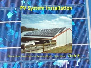
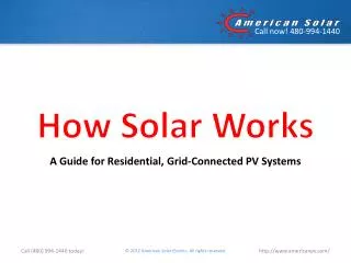
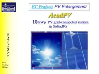
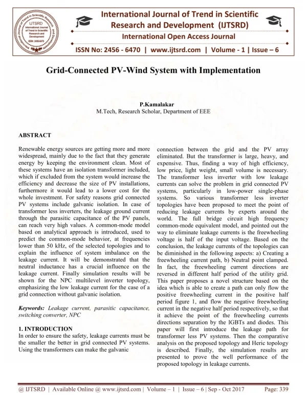
Renewable energy sources are getting more and more widespread, mainly due to the fact that they generate energy by keeping the environment clean. Most of these systems have an isolation transformer included, which if excluded from the system would increase the efficiency and decrease the size of PV installations, furthermore it would lead to a lower cost for the whole investment. For safety reasons grid connected PV systems include galvanic isolation. In case of transformerless inverters, the leakage ground current through the parasitic capacitance of the PV panels, can reach very high values. A common mode model based on analytical approach is introduced, used to predict the common mode behavior, at frequencies lower than 50kHz, of the selected topologies and to explain the influence of system imbalance on the leakage current. It will be demonstrated that the neutral inductance has a crucial influence on the leakage current. Finally simulation results will be shown for the NPC multilevel inverter topology, emphasizing the low leakage current for the case of a grid connection without galvanic isolation. P.Kamalakar "Grid-Connected PV-Wind System with Implementation" Published in International Journal of Trend in Scientific Research and Development (ijtsrd), ISSN: 2456-6470, Volume-1 | Issue-6 , October 2017, URL: https://www.ijtsrd.com/papers/ijtsrd2518.pdf Paper URL: http://www.ijtsrd.com/engineering/electrical-engineering/2518/grid-connected-pv-wind-system-with-implementation/pkamalakar<br>

E N D
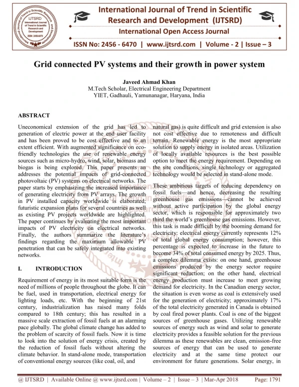
International Research Research and Development (IJTSRD) International Open Access Journal Connected PV-Wind System with Implementation Wind System with Implementation International Journal of Trend in Scientific Scientific (IJTSRD) International Open Access Journal ISSN No: 2456 ISSN No: 2456 - 6470 | www.ijtsrd.com | Volume 6470 | www.ijtsrd.com | Volume - 1 | Issue – 6 Grid-Connected PV P.Kamalakar M.Tech, Research Scholar, M.Tech, Research Scholar, Department of EEE ABSTRACT Renewable energy sources are getting more and more widespread, mainly due to the fact that they generate energy by keeping the environment clean. Most of these systems have an isolation transformer included, which if excluded from the system would increase the efficiency and decrease the size of PV installations, furthermore it would lead to a lower cost for the whole investment. For safety reasons grid connected PV systems include galvanic isolation. In case of transformer less inverters, the leakage ground current through the parasitic capacitance of the PV panels, can reach very high values. A common based on analytical approach is introduced, used to predict the common-mode behavior, at frequencies lower than 50 kHz, of the selected topologies and to explain the influence of system imbalance on the leakage current. It will be demonstrated that the neutral inductance has a crucial influence on the leakage current. Finally simulation results will be shown for the NPC multilevel inverter topology, emphasizing the low leakage current for the case of a grid connection without galvanic isolation. Keywords: Leakage current, parasitic capacitance, switching converter, NPC 1. INTRODUCTION In order to ensure the safety, leakage currents must be the smaller the better in grid connected PV systems. Using the transformers can make the galvanic Using the transformers can make the galvanic Renewable energy sources are getting more and more widespread, mainly due to the fact that they generate environment clean. Most of these systems have an isolation transformer included, which if excluded from the system would increase the efficiency and decrease the size of PV installations, furthermore it would lead to a lower cost for the For safety reasons grid connected PV systems include galvanic isolation. In case of less inverters, the leakage ground current through the parasitic capacitance of the PV panels, can reach very high values. A common-mode model cal approach is introduced, used to mode behavior, at frequencies kHz, of the selected topologies and to explain the influence of system imbalance on the leakage current. It will be demonstrated that the has a crucial influence on the leakage current. Finally simulation results will be shown for the NPC multilevel inverter topology, emphasizing the low leakage current for the case of a grid connection without galvanic isolation. connection between the gr eliminated. But the transformer is large, heavy, and expensive. Thus, finding a way of high efficiency, low price, light weight, small volume is necessary. The transformer less inverter with low leakage currents can solve the problem in systems, particularly in low systems. So various transformer less inverter topologies have been proposed to meet the point of reducing leakage currents by experts around the world. The full bridge circuit high frequenc common-mode equivalent model, and pointed out the way to eliminate leakage currents is the freewheeling voltage is half of the input voltage. Based on the conclusion, the leakage currents of the topologies can be diminished in the following aspects: a) C freewheeling current path, b) Neutral point clamped. In fact, the freewheeling current reversed in different half period of the utility grid. This paper proposes a novel structure based on the idea which is able to create a path can only flow the positive freewheeling current in the positive half period figure 1, and flow the negative freew current in the negative half period respectively, so that it achieve the point of the freewheeling currents directions separation by the IGBTs and diodes. This paper will first introduce the leakage path for transformer less PV systems. Then the co analysis on the proposed topology and Heric topology is described. Finally, the simulation results are presented to prove the well performance of the proposed topology in leakage currents. proposed topology in leakage currents. id and the PV array eliminated. But the transformer is large, heavy, and expensive. Thus, finding a way of high efficiency, low price, light weight, small volume is necessary. The transformer less inverter with low leakage currents can solve the problem in grid connected PV systems, particularly in low-power single-phase systems. So various transformer less inverter topologies have been proposed to meet the point of reducing leakage currents by experts around the world. The full bridge circuit high frequency mode equivalent model, and pointed out the way to eliminate leakage currents is the freewheeling voltage is half of the input voltage. Based on the conclusion, the leakage currents of the topologies can be diminished in the following aspects: a) Creating a freewheeling current path, b) Neutral point clamped. In fact, the freewheeling current directions are reversed in different half period of the utility grid. This paper proposes a novel structure based on the idea which is able to create a path can only flow the positive freewheeling current in the positive half period figure 1, and flow the negative freewheeling current in the negative half period respectively, so that it achieve the point of the freewheeling currents directions separation by the IGBTs and diodes. This paper will first introduce the leakage path for transformer less PV systems. Then the comparative analysis on the proposed topology and Heric topology is described. Finally, the simulation results are presented to prove the well performance of the current, parasitic capacitance, In order to ensure the safety, leakage currents must be the smaller the better in grid connected PV systems. @ IJTSRD | Available Online @ www.ijtsrd.com @ IJTSRD | Available Online @ www.ijtsrd.com | Volume – 1 | Issue – 6 | Sep - Oct 2017 Oct 2017 Page: 339
International Journal of Trend in Scientific Research and Development (IJTSRD) ISSN: 2456-6470 2.1 HB-ZVR Topology Another solution for generating the zero-voltage state can be done using a bidirectional switch made of one IGBT and one Diode Bridge. The topology is detailed in Fig. 3, showing the bidirectional switch as an auxiliary component with a gray background. This bidirectional switch is clamped to the midpoint of the dc-link capacitors in order to fix the potential of the PV array also during the zero-voltage vector when S1–S4 and S2–S3 are open. An extra diode is used to protect from short-circuiting the lower dc-link capacitor. During the positive half-wave, S1 and S4 are used to generate the active state, supplying a positive voltage to the load, as shown in Fig. 3. The zero-voltage state is achieved by turning on S5 when S1 and S4 are turned off, as shown in Fig. 4. The gate signal for S5 will be the complementary gate signal of S1 and S4, with a small dead time to avoid short- circuiting the input capacitor. By using S5, it is possible for the grid current to flow in both directions; this way, the inverter can also feed reactive power to the grid, if necessary. II. TRANSFORMER LESS TOPOLOGY ANALYSIS As discussed in previous works, the common-mode voltage generated by a topology and modulation strategy can greatly influence the ground leakage current that flows through the parasitic capacitance of the PV array. Generally, the utility grid does not influence the common-mode behavior of the system, so it can be concluded that the generated common mode voltage of a certain inverter topology and modulation strategy can be shown using a simple resistor as load. Therefore, in the case of simulations, only a resistive load is used, and the common-mode voltage is measured between the dc+ terminal of the dc source and the grounded middle point of the resistor as shown in Fig. 2. During the negative half-wave of the load voltage, S2 and S3 are used to generate the active vector and S5 is controlled using the complementary signal of S2 and S3 and generates the zero voltage state, by short- circuiting the outputs of the inverter and clamping them to the midpoint of the dc-link. During the dead time, between the active state and the zero state, there is a short period when the freewheeling current finds its path through the anti parallel diodes to the input capacitor while all the switches are turned off. This is shown in Fig. 5 and leads to higher losses, compared to the HERIC topology, where the freewheeling current finds its path through the bidirectional switch, either through S5 or S6, depending on the sign of the current. Figure 2: Test setup used for common-mode voltage measurement In the following, simulation results obtained using MATLAB/SIMULINK are shown. The simulation step size is 0.1 μs, with an 8-kHz switching frequency. Simulation parameters: Lf = 1.8 mH filter inductance; Cf = 2 μF filter capacitance; R = 7.5 Ω load resistance; Vdc = 350 V input dc voltage; Cdc = 250 μF dc-link capacitance; CG−PV = 100 nF parasitic capacitance of PV array; Fsw = 8 kHz switching frequency for all cases except that the switching frequency for unipolar Pulse width modulation (PWM) has been chosen to be Fsw = 4 kHz, so the output voltage of the inverter has the same frequency for all cases. CONCLUSION Transformer less inverters offers a better efficiency, compared to those inverters that have a galvanic isolation. On the other hand, in case the transformer is @ IJTSRD | Available Online @ www.ijtsrd.com | Volume – 1 | Issue – 6 | Sep - Oct 2017 Page: 340
International Journal of Trend in Scientific Research and Development (IJTSRD) ISSN: 2456-6470 omitted, the generated common-mode behavior of the inverter topology greatly influences the ground leakage current through the parasitic capacitance of the PV. Bipolar PWM generates a constant common- mode voltage, but the efficiency of the converter is low, due to the two level output voltage. By using unipolar PWM modulation, the output of the converter will have three levels, but in this case, the generated common-mode voltage will have high- frequency components, which will lead to very high ground leakage currents. This paper has introduced a transformer less topology and given an alternative solution for the bidirectional switch, used to generate the zero-voltage state. A NPCMLI is used to provide reduced harmonic voltage to the grid to reduce the harmonics at load current. REFERENCES [1] “Trends in photovoltaic applications: Survey report of selected IEA countries between 1992 and 2007,” IEA, Paris, France, Rep. IEA-PVPS T1-T17, 2008. phase photovoltaic systems,” IEEE Trans. Power Electron., vol. 22, no. 2, pp. 693–697, Mar. 2007. [5] B. Sahan, A. N. Vergara, N. Henze, A. Engler, and P. Zacharias, “A single stage PV module integrated converter based on a low-power current source inverter,” IEEE Trans. Ind. Electron., vol. 55, no. 7, pp. 2602–2609, Jul. 2008. [6] R. Gonzalez, E. Gubia, J. Lopez, and L. Marroyo, “Transformer less single-phase multilevel-based photovoltaic inverter,” Electron., vol. 55, no. 7, pp. 2694–2702, Jul. 2008. IEEE Trans. Ind. [7] J. Selvaraj and N. A. Rahim, “Multilevel inverter for grid-connected PV system employing digital PI controller,” IEEE Trans. Ind. Electron., vol. 56, no. 1, pp. 149–158, Jan. 2009. [8] E. Gubía, P. Sanchis, A. Ursúa, J. Lopez, and L. Marroyo, “Ground currents in single-phase transformer less photovoltaic systems,” Prog. Photo volt., Res. Appl., vol. 15, no. 7, pp. 629– 650, 2007. [2] J. M. Carrasco, L. G. Franquelo, J. T. Bialasiewicz, E. Galvan, R. C. P. Guisado, M. A. M. Prats, J. I. Leon, and N. Moreno-Alfonso, “Power-electronic systems for the grid integration of renewable energy sources: A survey,” IEEE Trans. Ind. Electron., vol. 53, no. 4, pp. 1002– 1016, Jul. 2008. [9] T. Kerekes, R. Teodorescu, and U. Borup, “Transformer less connected to the grid,” in Proc. APEC, Feb. 25– Mar. 1, 2007, pp. 1733–1737. photovoltaic inverters [10] T. Kerekes, R. Teodorescu, C. Klumpner, M. Sumner, D. Floricau, and R. Rodriguez, “Evaluation of three-phase transformer less photovoltaic inverter topologies,” in Proc. Eur. Conf. [3] “Photon Magazine, Apr. 2007. international,” The Photovoltaic [4] R. Gonzalez, J. Lopez, P. Sanchis, and L. Marroyo, “Transformer less inverter for single Power @ IJTSRD | Available Online @ www.ijtsrd.com | Volume – 1 | Issue – 6 | Sep - Oct 2017 Page: 341