Download
1 / 9
90 likes | 112 Views
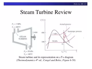
In recent years the electrical power generation from renewable energy sources, such as wind, is increasingly attracting interest because of environmental problem and shortage of traditional energy source in the near future. Wind turbine has a great impact on frequency regulation as a non conventional energy source. Frequency regulation is to regulate the power output of the electric generator within an area in response to changes in system frequency and tie line power. Therefore, the objectives of load frequency control are to minimize the transient deviations area frequency and tie line power interchange and to ensure their steady state errors to be zeros. Many controllers have already been proposed in earlier studies. This paper proposes a controller based on de loading of turbines for better dynamic response. This paper presents a solution to the LFC problem of wind turbine and steam turbine connected power system based on sudden load change and sudden wind speed variations in the power system. The dynamic model of the power system and the controller design based on the model are elaborated in the paper. Simulation results and frequency domain analyses proved that proposed scheme is attractive to the LFC problem in its stability and robustness. Faisal Mushtaq Raina | Gagan Deep Yadav "Frequency Regulation in Wind Turbine and Steam Turbine based Power System" Published in International Journal of Trend in Scientific Research and Development (ijtsrd), ISSN: 2456-6470, Volume-1 | Issue-6 , October 2017, URL: https://www.ijtsrd.com/papers/ijtsrd2412.pdf Paper URL: http://www.ijtsrd.com/engineering/electrical-engineering/2412/frequency-regulation-in-wind-turbine-and-steam-turbine-based-power-system/faisal-mushtaq-raina<br>

E N D
International Research Research and Development (IJTSRD) International Open Access Journal Frequency Regulation in Wind Turbine and Steam Turbine based Power System International Journal of Trend in Scientific Scientific (IJTSRD) International Open Access Journal ISSN No: 2456 ISSN No: 2456 - 6470 | www.ijtsrd.com | Volume 6470 | www.ijtsrd.com | Volume - 1 | Issue – 6 Frequency Regulation in Wind Turbine and Steam Turbine based Power System Frequency Regulation in Wind Turbine and Faisal Mushtaq Raina Gagan Deep Yadav Gagan Deep Yadav , Electrical Engineering , Yamunanagar, Haryana M.Tech Scholar, Electrical Engineering Department YIET, Gadhauli, Yamunanagar, Haryana Yamunanagar, Haryana M.Tech Scholar, Electrical Engineering Department Assistant Professor, Electrical Engineering Department YIET, Gadhauli, ABSTRACT In recent years the electrical power generation from renewable energy sources, such as wind, is increasingly attracting environmental problem and shortage of traditional energy source in the near future. Wind turbine has a great impact on frequency regulation as a non conventional energy source. Frequency regulation is to regulate the power output of the electric generator within an area in response to changes in system frequency and tie-line power. Therefore, the objectives of load frequency control are to the transient deviations (area frequency and tie power interchange) and to ensure their steady state errors to be zeros. Many controllers have already been proposed in earlier studies. This paper proposes a controller based on de-loading of turbines for better dynamic response. This paper presents a solution to the LFC problem of wind turbine and steam turbine connected power system based on sudden load change and sudden wind speed variations in the power system. The dynamic model of the powe the controller design based on the model are elaborated in the paper. Simulation results and frequency-domain analyses proved that proposed scheme is attractive to the LFC problem in its stability and robustness. I.INTRODUCTION The development of wind power in India began in the 1990s, and has significantly increased in the last few years. Although a relative newcomer to the wind industry compared with Denmark or the United States, India has the fifth largest installed wind power capacity in the world [1]. In 2009 rate was highest among the other top four countries. In 2012, despite a slowing global economy, India’s electricity demand continued to rise. Electricity shortages are common, and over 40% of the population has no access to modern energy services. So the renewable power had to come into effect. As of march 2016, renewable energy accounted for 19 percent of total installed capacity, up from 2 percent in 1995. Wind power accounts for about 70 percent of this installed capacity. By the end of August 2016, wind power installations in India had reached 32.29 GW [2]. The States like Tamil Nadu, Karnataka, Maharashtra and Gujarat have already been the leaders in terms of total wind installations and Rajasthan, Madhya Pradesh and Kerala are quickly catching up. Interestingly more than 95 percent of the nation’s wind energy development to date is concentrated in just five states in southern and western India – Tamil Nadu, Andhra Pradesh, Karnataka, Maharashtra, and Gujarat [LBNL, 2016]. These five states accounted for over 85% of the total installed capacity at the end of the last plan period. installed capacity at the end of the last plan period. electrical power generation from he development of wind power in India began in the 1990s, and has significantly increased in the last few years. Although a relative newcomer to the wind y compared with Denmark or the United States, India has the fifth largest installed wind power capacity in the world [1]. In 2009-10 India's growth rate was highest among the other top four countries. In 2012, despite a slowing global economy, India’s tricity demand continued to rise. Electricity shortages are common, and over 40% of the population has no access to modern energy services. So the renewable power had to come into effect. As of march 2016, renewable energy accounted for 19 installed capacity, up from 2 percent in 1995. Wind power accounts for about 70 percent of this installed capacity. By the end of August 2016, wind power installations in India had reached 32.29 GW [2]. The States like Tamil Nadu, Karnataka, nd Gujarat have already been the leaders in terms of total wind installations and Rajasthan, Madhya Pradesh and Kerala are quickly catching up. Interestingly more than 95 percent of the nation’s wind energy development to date is renewable energy sources, such as wind, is increasingly attracting environmental problem and shortage of traditional energy source in the near future. Wind turbine has a interest interest because because of of ion as a non- conventional energy source. Frequency regulation is to regulate the power output of the electric generator within an area in response to changes in system line power. Therefore, the objectives of load frequency control are to minimize the transient deviations (area frequency and tie-line power interchange) and to ensure their steady state errors to be zeros. Many controllers have already been proposed in earlier studies. This paper proposes a turbines for better dynamic response. This paper presents a solution to the LFC problem of wind turbine and steam turbine connected power system based on sudden load change and sudden wind speed variations in the power system. The dynamic model of the power system and the controller design based on the model are elaborated in the paper. Simulation results and domain analyses proved that proposed scheme is attractive to the LFC problem in its stability states in southern and Tamil Nadu, Andhra Pradesh, Karnataka, Maharashtra, and Gujarat [LBNL, 2016]. These five states accounted for over 85% of the total Keywords: Ancillary services, Frequency response, Emulating inertia, Primary frequency control, Wind turbines Frequency response, Emulating inertia, Primary frequency control, Wind From the above discussion it i community along with India is getting more and more community along with India is getting more and more From the above discussion it is clear that the world @ IJTSRD | Available Online @ www.ijtsrd.com @ IJTSRD | Available Online @ www.ijtsrd.com | Volume – 1 | Issue – 6 | Sep-Oct 2017 Oct 2017 Page: 197
International Journal of Trend in Scientific Research and Development (IJTSRD) ISSN: 2456-6470 interested about wind power. Wind power, however, is intermittent in nature and the frequency of supply is strongly related with the maintenance of active power balance in the network. Thus it is important to investigate the effect of wind power and the frequency of power system. The figure 1.1 shown below shows the current status of wind power capacity in India which is the main motivation behind this work. TABLE I: Total Global Installed Capacity (Up to December 2016) INSTALLED CAPACITY (MW) 145362 74471 44947 27151 23025 13603 COUNTRY China USA Germany India Spain UK Wind Power in India (MW) 11205 Canada 35 10358 France 30 25 8958 Italy 20 8715 Brazil 15 10 58275 Rest of the World 5 486790 Total 0 2001 2002 2003 2004 2005 2006 2007 2008 2009 2010 2011 2012 2013 2014 2015 2016 Different authors present different control schemes for frequency regulation in power system. A. Morinec et al. [2], develops an Active Disturbance Rejection Controller (ADRC) to control the frequency and tie line power error in a three area power system model. The ADRC controller takes the input output data from data from the system and compensates the disturbance. It also shows its effectiveness over conventional PID controller. M. Aldeen et al. [3], proposes a new robust filter based method to detect faults in the load frequency control loop. The proposed method can easily handle for faults taking place under different operating condition or any kind of external disturbances, like plant or sensor noise etc., H. Ryu et al. [4], shows the steam valve control is the direct method to control the kinetic energy stored in the generator and the designing of the stem valve has a significance effect on load frequency. The paper proposes a new modified PID controller to regulate the frequency. It has been tasted on two different systems and shown that the controller guarantees the stability of the LFC loop. A. Feliachi et al. [5], suggests a decentralized controller for interconnected power system with non-linearity. An exact feedback linearization control (FBLC) and observation decoupled state space (ODSS) modeling has been done and exact linearization is obtained. The paper proposes a H∞ controller to obtain robustness in the controller. This method applied on 3rdorder model and the desired stable response is obtained. Figure 1: Wind energy installed in India (2001- 2016) After analyzing the number of successful countries in promoting wind energy such as China, USA, Germany, Spain, India, Italy, France, etc., India is ranked at fifth position in wind energy among the leading countries. Wind power production capacity in key consideration for the assessment of wind energy level in order to achieve the next targeted wind power generation. Actually, utilization of wind power capacity came into real fact in 1997 with 940 MW capacities. An increment of 5.6% was obtained in the following year 1998. The increase in power generation on the basis of annual average data is observed. Clearly, it is a sign of improvement in the wind energy system for future. Wind atlas is helpful to determine the promising sites for large scale production of energy through wind turbine. As per C- WET data the total installable potential at 50 m level is 49130 MW. @ IJTSRD | Available Online @ www.ijtsrd.com | Volume – 1 | Issue – 6 | Sep-Oct 2017 Page: 198
International Journal of Trend in Scientific Research and Development (IJTSRD) ISSN: 2456-6470 I.Ngamroo et al. [6], shows a new strategy for LFC by introducing a solid-state phase shifter. It is located in series with the tie line which is capable of modulating the tie line power quickly. The paper has proposed a “H∞ Phase Shifter” for LFC loop. The effectiveness of the proposed controller has also been proved under several system uncertainties and sudden load change. Y. Moon et al. [7], proposes a new approach to the LFC problem. The paper gives a new idea of optimal tracking approach where the optimal feedback gains have been calculated for the new scheme that implies to the PID controller. The new LFC scheme with the modified PID controller has been tested on a single machine system and it has been shown that it improves the system damping and that the feedback of load disturbance signal helps to reduce the system oscillation B. Bakken et al. [8], presents a new Ramp following controller (RFC) is introduced in LFC for interconnected power system with HVDC connection. This controller ensures that the selected generators are automatically follows interconnected system with HVDC link. An interconnected model of Norway and Sweden has been taken and shown that how the proposed controller follows the load change of the HVDC. transformation of the DC quantities. It is similar to Park’s transformation, and it also solves the problem of AC parameters varying with time. Owing to the smooth air-gap in the induction motor, the self- inductance of both the stator and rotor coils are constant, whereas the mutual inductances vary with the rotor displacement with respect to the stator. Therefore the analysis of the induction motor in real time becomes complex due to the varying mutual inductances, as the voltage is not linear. A change of variables is therefore employed for the stator and rotor parameters to remove the effect of varying mutual inductances. This leads to an imaginary magnetically decoupled two phase machine. The orthogonally placed balanced windings, called d- and q- windings can be considered as stationary or moving relative to the stator. In the stationary frame of reference, the ds and qs axes are fixed on the stator, with either ds or qs axis coinciding with the a-phase axis of the stator. In the rotating frame, the rotating d-q axes may be either fixed on the rotor or made to move at the synchronous speed. Transformation from 3-phase stationary (a, b, c) to 2 phase stationary (ds , qs ) axes s qs V Setting =0, aligning qs -axis with a-axis (In case ds - axis is aligned with a-axis, replace sine with cosine and vice-versa). the load change in cos sin 0.5 cos sin 120 120 cos sin 120 120 V V V =2 as II. s Modelling and Control of Wind Energy Conversion System V 3 ds s bs 0.5 0.5 V 0 s cs A.Modelling of DFIG There are two ways to divide the complete control strategy of the machine, one is scalar control and the other is vector control. The limited uses of scalar control makes way for vector control. Although it is easy to execute the scalar control strategy, but the inherent coupling effect present gives slow response. This problem is overcome by the vector control, invented in the 1970s. An Induction Motor can be executed like a dc machine with the help of vector control. Vector control is employed to achieve a decoupled control of the active and reactive power. The basis of the vector control theory is d-q axis theory. Study of the d-q theory is essential for vector control analysis. d-q axis transformation (reference frame theory) dq0 or direct-quadrature-zero transformation is a mathematical transformation employed to simplify the analysis of three phase circuits, where three AC quantities are transformed to two DC quantities. The mathematical calculations are performed on the imaginary DC quantities and the AC quantities are again recovered by performing Figure 2: Phasor Diagram for abc to dq transformation 0.5 1 0 0.5 0.866 0.5 V V V s V V V as =2 qs s ds s 0.866 0.5 bs 3 0.5 cs 0 s an inverse @ IJTSRD | Available Online @ www.ijtsrd.com | Volume – 1 | Issue – 6 | Sep-Oct 2017 Page: 199
International Journal of Trend in Scientific Research and Development (IJTSRD) ISSN: 2456-6470 Transformation of 2-phase stationary (ds, qs) to synchronous 2-phase rotating axes (d, q) d-axis circuit 2 2 V V cos V sin qs qs s ds s 2 2 V V sin V cos ds qs s ds s Figure 6: d-axis equivalent circuit of DFIG in synchronous (d-q) frame Stator circuit equations in d-q frame 2 2 qs qs s qs e ds V R i ds ds s qs e qs V R i Where, ωψ is the back e.m.f .or speed e.m.f. due to rotation of axis. When the angular speed of the d-q frame i.e. e ωe = 0, the equation changes to stationary form. Rotor circuit equation in d-q frame qr r qr r e V R i dr s dr s e V R i If the rotor is blocked, i.e. ωr =0 then, V R i dr r dr r e qr V R i The vector control theory used in transforming the three phase quantities to two phase so that decoupled control could be achieved. The vector control was achieved using d-q transformation of quantities which lead to the equivalent circuit model for the d and q axis in the synchronous frame of reference. The stator, rotor and flux linkage expressions were then found out once the equivalent circuit can be achieved. 2 2 Figure 3: Transformation from ds, qs to d, q 2 2 V V cos V sin qs qs s ds s 2 2 V V sin V cos ds qs s ds s qr r dr r r qr r e dr qr Figure 4: Transformation from d, q to ds, qs B.Modelling of DFIG (in synchronous (d-q) frame) Stator circuit equations in ds-qs frame 2 2 2 qs qs s qs V R i V R i d-q equivalent circuit (DFIG) q-axis circuit 2 2 2 ds s ds ds III. WGs should respond to either the change of system frequency or to its rate of change (ROC).The response to the ROC of system frequency usually requires the contribution of only the kinetic energy of the WG for a limited time frame. This kind of response is called inertial, analogically to the behavior of any rotating electrical machine directly coupled to the grid. This is possible by shifting the operating point of WTG from its maximum tracking power to a reduced power level. This is called as de-loaded operation of WTG. The de-loaded operation reduces the output power of the WTGs, but increases the primary frequency contribution for long-term frequency deviation for any De-loading of Turbine Figure 5: q-axis equivalent circuit of DFIG in synchronous (d-q) frame @ IJTSRD | Available Online @ www.ijtsrd.com | Volume – 1 | Issue – 6 | Sep-Oct 2017 Page: 200
International Journal of Trend in Scientific Research and Development (IJTSRD) ISSN: 2456-6470 system events. However, de-loading is restricted between 10-20%, which depends on rotor speed limit constraints, available wind speed and converter rating On the other hand, when a WG is expected to follow the change of system frequency, some reserve has to be procured (through prior de-loading of the WG). The prior de-loading of the WG can be obtained either mechanically through pitch control of the wind turbine (WT) or kinetically through over-speeding of the rotor. De-loading of the WT can be achieved through proper manipulation of Cp, which is a function of the pitch angle and the rotational speed of the WT, it is mentioned that the implementation of both droop control and inertia emulator improves the dynamics of the system frequency response. Any generating unit to be used for primary frequency regulation availability of sufficient reserve capacity is an important requirement. Hence by controlling either one or both of these variables, the desired reserve can be obtained. The wind power plants have to maintain a certain level of power reserves. In this article, the wind power plant is equipped with a flywheel-based storage system to full fill the power reserve requirements set by the network operator. The article focuses on two main aspects. the definition of the control strategy to debate the wind turbines to provide a part of the required power reserves; and the coordinated regulation of the power reserves of the wind turbines and the flywheels while participating in primary frequency control. regulation enables the wind power plant to maintain the net level of power reserves set by the network operator while alleviating the need of de-loading the wind turbines. The performance of the proposed control schemes are shown by simulation [9]. grid. The flywheels are considered to be part of the WPP and provide part of the power reserves indicated by the system operator to the WPP. This way, the WPP participates in primary frequency control .Wind turbines are required to operate to some extent in a de- loaded mode depending on the level of power reserves of the flywheels, i.e. depending on their state of charge (SOC). Thus, the required power reserves by the system operator to the wind facility can be computed by the sum of the power reserves of the flywheels and the power reserves provided by the wind turbines. The latter can be deduced from the capability of the wind turbines to increase their generation level up to the maximum available power that can be extracted from the wind. Two contributions from the present work can be pointed out: The design of the central control system of the WPP and the local controllers of the wind turbines and the flywheels. These control systems are in charge of regulating maintained by the wind turbines and the flywheels under network disturbances and also in normal operating conditions. In case of a network disturbance i.e. of a system frequency deviation from its set-point, the power reserves of the wind turbines and the flywheels are immediately activated by their local controllers. This activation though, is supervised by the central control system of the WPP, and this is the main contribution of the article. the power reserves This coordinated The determination of the control method to allow the wind turbines to maintain a certain power margin from the maximum available power that can be extracted from the wind. This control method is included in the local controller of the wind turbines. Several energy storage devices suitable for frequency control - related tasks can be found. Considers the application of large scale storage systems like pumped-hydro, compressed-air and hydrogen-based systems. Also, it is worth noting that batteries, flow batteries and those storage devices with very high ramp power rates and short time responses like Superconducting Magnetic Energy Storage (SMES) and flywheels are specially well-suited for this application [9]. Remarkable flywheels are their very high ramp power rates, high reliability and energy efficiency (around 90%. On the other hand, standing losses are non-negligible. In fact, self-discharge rates are about 20% of the stored capacity per hour. This work considers the inclusion of a flywheel-based storage plant in the point of common coupling (PCC) of a WPP with the external As discussed in the following, the method applied to de-load a WG is crucial in its performance when providing frequency response. De-loading through rotational speed control De-loading through pitch control characteristics of A.De-loading Through Rotational Speed Control: If wind speed is considered constant and the pitch angle does not change, a requested amount of de- loading is achieved at two alternative operating points. Compared to the MPT, the left point is of decreased and the right point of increased rotor speed. In it is explained why de-loading via under-speeding @ IJTSRD | Available Online @ www.ijtsrd.com | Volume – 1 | Issue – 6 | Sep-Oct 2017 Page: 201
International Journal of Trend in Scientific Research and Development (IJTSRD) ISSN: 2456-6470 results to detrimental behavior of the WG regarding the LFC problem and how it also threatens the balance of the mechanical system. Therefore, under speeding will be ignored in the course of this paper. In most of its realizations, de-loading via over-speeding is executed through the control scheme of Fig.7.The technique specifically measurement or estimation. Moreover, at wind speeds even below nominal, it is implied that pitch control assists over-speeding. The linear approximation of the MPT LUT and the measurement/forecast as input can be inaccurate. Increased wear of the pitch control system might also be a consideration requires wind-speed Figure 9 Strategies to release a power margin. Pitch angle control of the wind turbine is designed much like governor control of synchronous machine in this part to make the wind power plant have a long- term frequency regulation capability. The pitch control limits the active power to a value lower than its nominal value, The resulting active power reserve can be delivered by decreasing the pitch angle as system frequency drops, so that the turbine can extract more mechanical power from wind flow. It should be noted that for any given wind speed there is an optimal turbine rotational speed out corresponding to the optimal strategy. When de-loading through pitching it is desirable to maintain this optimal speed, otherwise the turbine would have to be accelerated under speeding case) or decelerated (over speeding case). use of wind speed Figure.7 WG de-loading and LFC control scheme B.De-loading Through Pitch Control: for a given wind speed and assuming that the rotor speed does not change (vertical line from MPT down to pitching), a requested amount of de-loading is achieved at an operating point corresponding to a greater pitch angle. A generic controller of this type is shown in Fig. 8. IV. As mentioned before the proposed system is subjected with variable wind speed and load, that causes the frequency deviations in whole system. The various results has been shown as following: Wind turbine Power Characteristics RESULTS Wind turbine has rated output power at 12 m/sec and below this the power output reduces and above this power increases which causes the change in frequency. Figure 9 the variations of wind turbine output power vs wind speed characteristics Figure 8 Pitch-controlled de-loading control schemes. The pitch angle controller was first suggested into directly drive the de-loading of a WT. Consequently, LFC response would be provided through a droop characteristic of frequency versus pitch angle. There is no LUT and a signal of increase or decrease is directly inputted to the pitch angle controller. Likewise, in the LFC scheme of Fig. 4.7, the droop drives the pitch angle instead of the active power adjustment DPLFC. Precise setting of a requested power margin, uniform LFC throughout the power system and specific output power regulation of the WG are limited, since the pitch angle (and not a power reference) controls both the de-loading and the frequency response of the WG. Figure 9 Wind turbine Power-Speed characteristics. @ IJTSRD | Available Online @ www.ijtsrd.com | Volume – 1 | Issue – 6 | Sep-Oct 2017 Page: 202
International Journal of Trend in Scientific Research and Development (IJTSRD) ISSN: 2456-6470 Wind Speed Profile The wind profile fed to the wind turbine is shown in figure 10 There is step change in the wind speed for each 100 seconds and varies in between 10 m/sec to 12 m/sec. Figure 13 Delta P for area-II Frequency Profile and Electromagnetic Torque As the system is interconnected, the change in frequency affects in both areas. Figure 14 shows the frequency profile of the system when there is distrubances happens. The frequency deviations is withtin 0.1% tolerance range. So it can be said the the proposed control scheme effectively control the frequency deviations. Figure 15 shows the electromagnetic torque produced by wind turbine. As the wind speed changes there is change in the electromagnetic torque produced by the wind turbine-generator system. Figure 10 Wind speed profile. Voltage at PCC The voltage is one of the main propority of power quality and voltage value should be constant irrespective of variations in load and wind speed. Figure 11 shows the voltage level at point of common coupling (PCC). There is almost zero deviations in voltage after the distrubance imposed on the system. Figure 11 Voltage at PCC. Figure 14 Frequency deviations in the system. Contol signal (Delta P) The variations in frequency is controlled by inerial emulation of the power system through control command. The control signal is generated by taking the input as change in frequency and rate of change in frequency (ROC). The inertial power is then fed to or abosrbed in according to frequency rise aor frequency dip. Figure 12 and 13 show the waveform for delta P for area-I and area-II respetively. Figure 15: Electromagnetic Torque Figure 12 Delta P for area-I @ IJTSRD | Available Online @ www.ijtsrd.com | Volume – 1 | Issue – 6 | Sep-Oct 2017 Page: 203
International Journal of Trend in Scientific Research and Development (IJTSRD) ISSN: 2456-6470 been given. Participation of DFIG based wind generators in frequency regulation and automatic generation control (AGC) services in multi-area control systems is a complex problem. The DFIG contrary to fixed speed WT could participate and improve the frequency performance and support conventional generation in frequency regulation services by reduction in ACE in each area. COMPARISON OF CHARACTERISTICS WITH AND WITHOUT CONTROL Here presents a small-perturbation transfer function model for a two-area power system, each area equipped with DFIG based wind generators. As in the previous chapter, integral absolute error based optimal tuning of the DFIG controllers is carried out. A detailed simulation result has also given to understand the behavior of frequency with load deviation. From the above results it is clear that proposed controller gives better stability than the without controller. The proposed controller throughout gives better stability in all the cases discussed above and almost in every case the settling time and area control error (ACE). Figure 16 Different parameters without frequency control REFERENCES [1]Elgerd Ol. Fosha C,”Optimal megawatt frequency control of multi area electric energy systems”, IEEE Trans Electric Power Apparatus System, vol.PAS-89, pp.556-63, 1970 [2]Adil Usman BP Divakar “Simulation study of load frequency control of single and two area systems”. IEEE Global Humanitarian Technology Conference, pp.214-219, 2012 [3]H.Bevrani, Y.Mitani and K.Tsuji, “Robust decentralised load frequency control using an iterative linear matrix inequalities algorithm”, IEE Pro. Gener. Transm. Distrib., vol.151, no.3, pp.347-354, 2004. [4]Wind Vision for Canada”, Recommendations for Achieving Canada’s Wind Energy Potential, Report by the Canadian Wind Energy Association (CanWEA). [5]Quick Facts about Wind Energy, Canadian Wind Energy Association http://www.canwea.ca.2016, http://www.canwea.ca/pdfs/CanWEA- WindVision.pdf. [6]A. Morinec, and F. Villaseca, “Continuous-Mode Automatic Generation Control of a Three-Area Power System”, The 33rd North American Control Symposium, pp. 63–70, 2001. [7]M. Aldeen, and R. Sharma, “Robust Detection of Faults in Frequency Control Loops,”IEEE Figure 17: Different parameters with frequency control From the figures 16 and 17 it can be concluded that there is more deviations in rotor speed as the disturbances occurs in the system when no inertial de- loading technique is applied. But when the proposed system regulates the frequency within acceptable limits and effectively control the frequency and rotor speed deviations. V. This paper proposed an inertial emulation based de- loading frequency controller for interconnected power systems. The design approaches of system have been explained in detail. Two area power systems were established and utilized to test the stability, reliability and robustness of system in the presences of power load changes, and system parameter variations. The proposed controller was simulated on two different types of load change and the simulation results have CONCLUSIONS (CanWEA), @ IJTSRD | Available Online @ www.ijtsrd.com | Volume – 1 | Issue – 6 | Sep-Oct 2017 Page: 204
International Journal of Trend in Scientific Research and Development (IJTSRD) ISSN: 2456-6470 Transactions on Power Systems, vol. 22, no. 1, pp. 413–422, Feb. 2007. [8]Y. Moon, H. Ryu, B. Choi, and H. Kook, “Improvement of System Damping by Usingthe Differential Feedback in the Load Frequency Control,” IEEE Power EngineeringSociety 1999 Winter Meeting, vol. 1, pp. 683–688, Feb. 1999. [9]Chittaranjan Pradhan Bhende, “Enhancement in Primary Frequency Contribution using Dynamic D-lloading of wind turbine”, Vol.48, 2015, pp 013-018. and Chandrashekhar @ IJTSRD | Available Online @ www.ijtsrd.com | Volume – 1 | Issue – 6 | Sep-Oct 2017 Page: 205