Download
1 / 11
110 likes | 132 Views
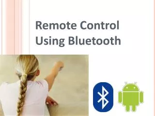
The objective of our project is to develop an Exploiting Bluetooth on Android mobile devices for home appliances control appliances control application. Mobile deviceshave been integrated into our everyday life consequently, home automation is becoming increasingly prominent features on mobile devices .We have developed a security system that interfaces with an android mobile devices.The mobile device will be communicate through Bluetooth by the shortest way. The mobile application can be loaded onto any compatible device, and once loaded, interface with the appliances easily .commands to ON,OFF,or check the status of the appliance to which is installed can be sent quickly from the mobile device via a simple, easy to use GUI. The security system then acts on these commands, taking the appropriate action and sending a confirmation back to mobile device. This system can also tell the user if any of appliances is ON or OFF G. Naveen Balaji | K. Saravanan | R. Poorani | T. Vishnu Priya | R. Reka Raj "Advanced Security System using PIC through Bluetooth" Published in International Journal of Trend in Scientific Research and Development (ijtsrd), ISSN: 2456-6470, Volume-1 | Issue-5 , August 2017, URL: https://www.ijtsrd.com/papers/ijtsrd2350.pdf Paper URL: http://www.ijtsrd.com/computer-science/computer-security/2350/advanced-security-system-using-pic-through-bluetooth/g-naveen-balaji<br>

E N D
International Journal of Trend in Scientific Research and Development (IJTSRD) UGC Approved International Open Access Journal ISSN No: 2456 - 6470 | www.ijtsrd.com | Volume - 1 | Issue – 5 Advanced Security System using PIC through Bluetooth G. Naveen Balaji Assistant Professor, Department of ECE, SNS College of Technology, Coimbatore, India Coimbatore, India T. Vishnu Priya UG student, Department of ECE, Coimbatore Institute of Technology, Coimbatore, India ABSTRACT K. Saravanan R. Poorani UG Student, Department of ECE, SNS College of Technology, UG Student, Department of ECE, SNS College of Technology, Coimbatore, India R. Reka Raj UG student, Department of ECE, United Institute of Technology, Coimbatore, India The objective of our project is to develop an Exploiting Bluetooth on Android mobile devices for home appliances control application. Mobile devices have been integrated into our everyday life consequently, home automation is becoming increasingly prominent features on mobile devices .We have developed a security system that interfaces with an android mobile devices. The mobile device will be communicated through Bluetooth by the shortest way. The mobile application can be loaded onto any compatible device, and once loaded, interface with the appliances easily .commands to ON, OFF, or check the status of the appliance to which is installed can be sent quickly from the mobile device via a simple, easy to use GUI. The security system then acts on these commands, taking the appropriate action and sending a confirmation back to mobile device. This system can also tell the user if any of appliances is ON or OFF our daily life that used to control the home appliances. Mobile devices have been integrated in to our everyday life .consequently home automation becoming increasingly prominent features on mobile devices. appliances control Our project consists of microcontroller, LCD display, keypad, UART, Bluetooth modem relay, relay driver and android smart phone. The status information is wirelessly transferred to the mobile and the same is displayed at the LCD display. Thus the Bluetooth functionality in the android mobile phone has been effectively leveraged for implementing the home appliances system and as the android phone has been effectively leveraged for implementing the home appliances system and as the android phone is hand held; it is easy to get notifications like lock status etc. At the application itself. The microcontroller was connected in all blocks of the circuit. The block diagram consists of Transmitter and Receiver. Android smart phone is connected to the transmitter and GSM is connected to the receiver. The components placed in block diagram like micro controller UART (Universal Asynchronous Receiver and Transmitter), GSM (Global System for Mobile Communication), LCD 1.INTRODUCTION The objective of our project is to develop an exploiting GSM (Global System for Mobile communication) on android mobile devices for home appliances control application. Mobiles are used in @ IJTSRD | Available Online @ www.ijtsrd.com | Volume – 1 | Issue – 5 | July-Aug 2017 Page: 675
International Journal of Trend in Scientific Research and Development (IJTSRD) ISSN: 2456-6470 (Liquid Crystal Display), relay driver, and power supply. machines and other communication equipment and home robots such as automatic vacuum cleaners. In our Project we are using 4.0 version android it is “blue tooth”. The 12v electromagnetic relay used. The signal is transmitted from the android smart phone and signal is received by gsm. Gsm 900 is used. By using we can control the devices maximum up to 35 kilometres home appliances. The fundamental components well designed home automation system include a computers withappropriate programming the various devices and systems to be controlled, interconnecting cables or wireless links a high-speed internet connection, and an emergency backup power source for the computers its peripherals ‘and the essential home systems. 1.1ANDROID Fig.1 Android Mobile 1.2 WORKING PRINCIPLE Android it is one of the operating system developed in last 15 Years. Android increment was founded in rich miner, nick sears and Chris white in the year 2003. The android has many versions it is also an open mobile phone platform that was developed by Google later by the open handset alliance. Google defines android as ‘Software stack’. The software stack made as operating system platform while everything is running thee middleware (the programming allows application to talk to a network and to another )and the application (the actual programs that the phones will run).in short the android software that will make an android phone an android. Fig.2 Home Auto Machine 1.4 PCB (PRINTED CIRCUIT BOARD) The printed circuit board (PCB) mechanically supports and electrically components wing conductive tracks. Pads other features etched from copper sheets laminated on to a non-conductive substrate. PCB‘S can be single sided (one copper layer), double side (two copper layer) or multilayer conductors on different layers are connected with plated through holes called visa. Advanced PCB‘S may contain components like capacitor, resistors or active devices-embedded device in the substrate. connects electronic 1.3HOME AUTOMATION It is the use it can scheduling and automatic operation of water sprinkling, heating, and air conditioning, window coverings, security systems, lighting ,food preparation etc….home automation may also allow vital home function to be controlled of one or more computers to control basic home functions and features automatically and sometimes remotely. An automation home is sometimes is called a ”smart home” remotely from anywhere in the world using a computer connected to the internet. Besides the function already mentioned, remote control can be extended to telephone and answering machines, fax PCB is used in all but the simplest electronic products. Alternatively to the PCB include wire wrap and point to point constriction. PCB'S required additional design effort to layout the circuit. But once that done, the manufacture and assembly can use automation PCB can manufacture circuits less expensively and more quickly than other wiring methods because component mounting and wiring is @ IJTSRD | Available Online @ www.ijtsrd.com | Volume – 1 | Issue – 5 | July-Aug 2017 Page: 676
International Journal of Trend in Scientific Research and Development (IJTSRD) ISSN: 2456-6470 1.5.2 PANELIZATION done with one component. Furthermore, operator wiring errors are eliminated It is a procedure used to handle PCB which would otherwise be too small to process. When the board has only copper connections and no embedded components it is more correctly called a “printed wiring board" (PWB) or etched wiring board. Although more accurate the term printed wiring board has fallen in to disuse. A PCB populated with electronic components called a “printed circuit assembly" (PCA)/ (PCBA). The term PCB is used informally both for bare and assembled boards. 1.5.3 COPPER PATTERNING The pattern in the manufactures PCB cam system is usually output on a photo mask. 1.5.4 PATTERNING METHOD BY VOLUME It has many volumes like large volume, small volume, and hobbyist. 1.5.5 CHEMICAL ETCHING It is usually done by ammonium per alphabet or ferric chloride. 1.5.6 OPTICALINSPECTION (AOI) INNER LAYER AUTOMATED The inner layer is given complete machine inspection before lamination process because after the lamination process the mistakes cannot be corrected. 1.5.7 LAMINATION Fig.3 Designing Of PCB Multilayer PCB has trace layers inside the board .Lamination is done by placing the stack of materials in a press and applying pressureand heat for a period of time. PCB was initially a fully manual process done on clear Mylar sheets at a scale of usually 2 or 4 times the desired size. The schematic diagram is first converted in to a layout of components pin pads, then traces were routed to provide the required interconnections, pre-printed non-reproducing Mylar grids assisted in layout, and rub-on dry transfers of common arrangements of circuit elements (pads, contact finger integrated circuits profiles, and so on) helped standardize the layout. Traces between devices were made with self CC Cadhesive tape. The finished layout “artwork” was reproduced on the resist layers of the blank coated copper-clad boards. 1.5.8 DRILLING Holes and typically drilled with PCB board with PCB board with required diameter. 1.5.9 PLATING AND COATING PCB plated with solder, tin, or gold over nickel as a resister for etching away the unneeded underlying copper. then photographically 1.5.10 SOLDER RESIST APPLICATION 1.5 MANUFACTURING STEPS OF PCB Areas that should not per soldiered may be covered with solder resist. 1.5.1 PCB CAM It is often printed on one or both sides of the PCB. Manufactures never use the file directly on their equipment but always read them in their cam system. PCB cannot be manufactured progressively without cam system. 1.5.11 LEGEND PRINTING It is often printed on one or both sides of the PCB. @ IJTSRD | Available Online @ www.ijtsrd.com | Volume – 1 | Issue – 5 | July-Aug 2017 Page: 677
International Journal of Trend in Scientific Research and Development (IJTSRD) ISSN: 2456-6470 1.5.12 BARE BOARD TESTING Of tapping on the resistive element and resistors with a movable tap (“potentiometer”) either adjustable by the user of equipment or contained within are used. It used to check whether the connections are correct or not. 1.5.13 PROTECTION AND PACKING PCB intended for extreme environments often have conformal coating which is applied by dipping or spraying after the components are have soldered and finally packed 1.6 RESISTOR The resistor is a two terminal electronic components designed to oppose an electronic current by producing a voltage drop between its terminals in proportion to the current that is in accordance with ohm’s law Fig 5: Colors Of The Resistors Ohms law V=IR 1.6.1 IDENTIFYING THE RESISTORS The resistance is equal to the voltage drop v across the resistor divided by the current through the resistor. resistor are characterized primarily by the resistance and the power they can dissipate other components include temperature co-efficient, inductance, practical resistor can be made of resistive wire and various compounds and films and they can be integrated in to hybrid printed circuits Separate the resistors from all other components and place them on the bench. So that the gold band indicates the resistors have a tolerance of 5%.in other words they are made accurate than the older 10% types. The gold band does not concern us in this course but it does tell us which way around to hold the resistors so that the color bands can be read correctly only 10 different colors are used for all resistors noise and The size bad position of leads is relevant must be physically large enough not to overheat when dissipating their power variable resistor adjustable by changing the position Hold the resistor so that 3 color band are to the left and the right hand band is either gold or silver. The first color gives the first digit of the resistance. The second color gives the second digit in the answer. The third color gives the number of zeros in the answer. There are only 12 resistors in each decade and they have the following first two colors. 1.7CAPACITOR Fig 4: Resistor Fig 6: Charging Capacitor @ IJTSRD | Available Online @ www.ijtsrd.com | Volume – 1 | Issue – 5 | July-Aug 2017 Page: 678
International Journal of Trend in Scientific Research and Development (IJTSRD) ISSN: 2456-6470 2.2 WORKING PRINCIPAL In the capacitors the plates store the energy sort like a battery the big different between the batteries and capacitors works at all voltages up to its maximum safe rating. Basically when DC voltage source is applied to the capacitor is equal to the applied voltage the current flow stops. When the current stops flowing from the power supply to the capacitor .the capacitor is discharge up. After the capacitor is charge it can be discharged in like a battery. The transmitter produces the short duration high power radio frequency pulses of energy that and radiated in to space by the antenna. The transmitter side have the android smart phone to transmit the signal. The transmitter is required to have the following technical and operating characteristics: The transmitter must have the ability to generate the required mean power and the required peak power. The rather transmitter must have a suitable radio frequency band width The transmitter must have a high radio frequency stability to meet signal processing requirements The transmitter must be easily modulated to meet wave from design requirements. The transmitter must be efficient reliable and easy to maintain the life expectancy and the cost of the output device must be acceptable. The only problem is that the capacitor will not want to hold its charge for more than a few minutes. These present obvious problems using the capacitors as a storage devices. There are many materials make capacitors these includes the metals such as aluminum, titanium and silver is the materials used for making the capacitors. 1.8 HOME APPLIANCES USED IN OUR PROJECT 1.8.1 FAN The coolant fan is used in our project it is controlled by the 5 volts, 2.3 RECEIVER 1.8.2 LIGHT The normal home use bulb is used it is controlled by 40, 60,100….volts. II. BLOCK DIAGRAM 2.1 TRANSMITTER Fig 8: Receiver 2.4 WORKING PRINCIPLE The receiver is the listener, reader or observer in the communication process. “Audience”. In communication process the role of the receiver is believable as important as that of sender. The receiver has five important steps as follows: Another name is Fig 7: Transmitter @ IJTSRD | Available Online @ www.ijtsrd.com | Volume – 1 | Issue – 5 | July-Aug 2017 Page: 679
International Journal of Trend in Scientific Research and Development (IJTSRD) ISSN: 2456-6470 RECEIVER UNDERSTAND ACCEPT USE AND GIVE FEEDBACK Without these steps the communication will not be successful. The sender transmitts a message and the receiver decodes a message. The receiver is the destination of the message.the task is to interpret the senders message both verbal and non verbalwith as little distortion or noise is possible .The receiver is close-mineded and unreceptive to new and different ideas . the receiver side consists of pic micro controller (PIC 16F877A),GSM (Global System For Mobile Communication),UART(Universal Asynchronous Receiver and Transmitter),power supply,bluetooth,relay driver. The signal transmitted by the android smart phone is received by the receiver. III. BLUETOOTH 4.1 CIRCUIT DIAGRAM EXPLANATION It starts from power supply section. We have the 12V AC input from the secondary output of the transformer. This is fed to the bridge rectification section that converts AC supply in to DC supply. This is done by four IN4007, 1A diodes in bridge configuration, then on the dc output of this section a large capacitor (IOOOMF, 10V) and another small 100nF capacitor is there to filter the DFC supply and remove all the AC components from it. This is because we are operating predigital circuitry that fails to operate on unregulated and unfiltered supply. After the DC supply is being filtered as it is unregulated is turned in to regulated 5V DC supply using LM7806 &7812 regulator. Bluetooth is a wireless devices used at the particular distances. it is specification IEEE (802.15.1)for the use of low power radio communications to link phones, computers and other network devices over short distance without wire The name Bluetooth is borrow from ”Haraid Bluetooth” a king in Denmark lived more than 1,000 years ago. Bluetooth technology was designed primarily to support simple wireless networking of personal consumer devices and peripheral’s including all phone PDAS ,and wireless signals transmitted with Bluetooth cover short distance typically up to 30MBPS feet (10 meters).Bluetooth devices are generally communicate at less than 1MBPS 4. CIRCUIT DIAGRAM @ IJTSRD | Available Online @ www.ijtsrd.com | Volume – 1 | Issue – 5 | July-Aug 2017 Page: 680
International Journal of Trend in Scientific Research and Development (IJTSRD) ISSN: 2456-6470 Again after that a small 1OOnF capacitor is there to filter the regulated DC supply. A regulated 3.3volt supply is also derived from another regulator is the input is fed from the regulated 5V output of the IC 7806&7812 voltage regulator. Regulated 5Volt supply is needed to drive the microcontroller, relays and all the sensors while 3.3Volts is required by the Bluetooth DC supply it is a single layered PCB it consists of 1OOOMF capacitor, 22MF and 1OMF capacitor and diode IN1007, and transistor 7805GT and resistor of 330 ohms, Bluetooth (12v) it is a double layered PCB , power supply(AC to DC 5V regulator and DC 12v is directly given to the relay driver, LCD (liquid crystal display) (12v) DC supply it is a double layered PCB and the IC is fully 5V supply are used as receivers. The signal transmitted by the android smart phone was received by the receiver side, the android 4.0version (Blue Term) is used in our project it supports the multi touch software’s. The working principle of this block diagram is that the signal transmitted by the android smart phone was received by the GSM (global communication) it covers the distance maximum up to 35 kilometers and it was connected to the universal asynchronous receiver and transmitter) UART is used for the communication between the devices and the relay is the controlling device it controls all the devices like fan, light... and finally the message was received by the android phone by using the GSM, . UART &transmitter) module to operate. After that the regulated supply is fed to all the sensors, relays and the microcontroller. (universal asynchronous receiver There are five sensors are being directly interfaced to microcontroller. To sense the light intensity we use two LDR sensor that light dependent resistors interfaced to the ADC input of the microcontroller. One pin of the LDR is connected to 330k resister and other tied to the ground. This creates the potential difference between the circuits and fed to the pin A3 and A2 of the microcontroller. To sense the temperature the two solid state semiconductor temperature sensors from analogy devices also interfaced to the ADC input of the microcontroller. The two pins are connected to the power supply. system for mobile 5. PIC MICRO-CONTROLLER (PIC 16F877) This microcontroller has only 35 single word instructions to learn. All single word cycle instructions except for program branches, which are two cycles. Operating speed in dc 20 MHZ clock input dc-200ns instruction cycle. 2000*14 words of program memory and 128*8 bytes of data memory that is RAM. It has interrupt capabilities and eight- level deep hardware. It contains of direct, indirect and relative addressing modes. It operates on 5v power supply. And the third pin is the output the switches are used to sense the home appliances are on/off if it is not off the switch will be in open state. To display the messages the sensor values 16*2 character LCD (liquid crystal display) is used in 4bit mode to port B of them. To sense the presence and the motion the PIR (PYROELECTRIC INFRARED) is used. BC 107 transistor circuit is interfaced with digital output of the microcontroller. The H-bridge circuit is used to drive the DC motor in both directions. The three transistors use the simple switch only and all the four transistors are protected by limiting the current by R1- R4 resistors. 4.2 ANDROID HOME AUTOMATION EXPLANATIONAND WORKING OF The components used in our project are android smart phone as transmitter. And the transformer the step- down transformer is used (AC) it is (12v) 1AMPS, microcontroller (5v) DC supply it is a single layered PCB it consists of crystal oscillator KD54-000 , capacitor C5578, a GSM(global system for mobile communication) (12V)DC supply it is a double layered PCB, UART (universal asynchronous receiver and transmitter) (12V) DC supply , relay driver (12v) Fig.10: Pin Diagram (Pic16f877a) @ IJTSRD | Available Online @ www.ijtsrd.com | Volume – 1 | Issue – 5 | July-Aug 2017 Page: 681
International Journal of Trend in Scientific Research and Development (IJTSRD) ISSN: 2456-6470 The most pins are multi-functional. For example, designator RA3/AN3/Vref+/C1IN+ for the fifth pin specifies the following functions RA3 Port A third digital input/output AN3 Third analog input Vref+ Positive voltage reference C1IN+ Comparator C1positive input This small trick is often used because it makes the microcontroller package more compact without affecting its functionality. These various pin functions cannot be usedsimultaneously, but can be changed at any point during operation. Fig 10: GSM A GSM modem can be external device or a PC card/ Pcmcia card. Typically, an external GSM modem is connected to a computer through a serial cable or a USB cable. A GSM modem in the form of a PC card! Pcmcia card is designed for use with a laptop computer, It should be inserted in to one of the PC card/Pcmcia card slots of a laptop computer. Like GSM mobile phone, a GSM modem requires a SIM card from a wireless J carrier in order to operate. 6. GSM (GLOBAL SYSTEM FOR MOBILE COMMUNICATION) GSM (Global System for Mobile Communications, originally Group Special Mobile), is a standard set developed by the European telecommunication standard (ETSI) to describe technologies for second generation (or "20") digital cellular network. Developed as a replacement for first generation analog cellular networks, the GSM standard originally described a digital, circuit switched network optimized for duplex(communication) telephony. soThe standard was expanded over time to include first circuit switched data transport, then packet data transport via GPRS. Packet data transmission speeds were later increased via EDGE. The GSM standard is succeeded by the third generation (or "30“) UMTS standard developed by the 3GPP. GSM networks will evolve further as they begin to incorporate fourth generation (or “4G") LTE advanced standards. "GSM" is a trademark owned by the GSM association. The GSM Association estimates that technologies defined in the GSM standard serve 80% of the world‘s population, encompassing more than 5 billion people across more than 212 countries and territories, making GSM the most ubiquitous of the many standards for cellular networks. As mentioned in earlier sections of this SMS tutorial, computers use AT commands to control modems. Both GSM modems and dial-up modems support a common set of standard AT commands. The GSM can use just like a dial-up modem. In addition to the standard AT commands, GSM modems support an extended set of AT commands. The extended AT commands are defined in the GSM standards. With the extended AT commands, do things like: voice Reading, writing and deleting SMS messages Sending SMS messages Monitoring the signal strength. Monitoring the charging status and charge level of the battery Reading, writing and searching phone book entries, The number of SMS messages that can be processed by a GSM modem per minute is very low only about six. to ten SMS messages per minute This GSM modem is a highly flexible plug and play GSM 850 900 / GSM 1800 / GSM 1900 modem for direct and easy integration R8232, voltage range for the power supply and audio interface make this device perfect solution for system integrators and single user. It ‘also comes with license free integrated Python. Python is a powerful easy to learn programming language. Such a Python driven terminal is 5 times better and faster and 5 times cheaper than standard PLC/RTU with communication interface and external GSM f GPRS The GSM modem is a wireless modem that works with a GSM wireless network. A wireless modem behaves like a dialup modem. The main difference between them is that a dial-up modem sends and receives data through a fixed telephone line while a wireless modem sends and receives data through radio waves @ IJTSRD | Available Online @ www.ijtsrd.com | Volume – 1 | Issue – 5 | July-Aug 2017 Page: 682
International Journal of Trend in Scientific Research and Development (IJTSRD) ISSN: 2456-6470 8. POWER SUPPLY modem. Voice, Data/Fax, SMS, DTMF, GPRS, integrated TCP/IP stack, RTC and other features like the GSM / GPRS modules on this home page. A power supply is a device that supplies electrical power to one or more electric loads or appliances. The term is most commonly applied to devices that convert one form of electrical energy to another, though it may also refer to devices that convert another form of energy to electrical energy. Low voltage DC power supplies are commonly integrated with their loads in devices such as computers and household electronics. Rectifier is used to convert alternating voltage into pulsating direct voltage. A small remaining unwanted alternating voltage component at mains or twice mains power frequency depending upon whether half or full wave rectification is used ripple is unavoidably Super imposed on the direct output voltage. For purpose such as charging batteries the ripple is not a problem, and the simplestUNregulated mains-powered DC power supply circuit consists of transformer driving a single diode in series with a resistor. 6.1 GSM FEATURE GPRS class 10:max 85.6 KBPS(down link) PBCCH support Coding schemes CS1,2,3,4 CDS up to 14.4 KBPS USSD 7. RELAY Relays are used throughout the most of appliances that comes in different sizes for suitable appliances. And also it is used as remote control switches. A typical vehicle can have 20 relays or more. It is purely for switching purpose. All relays operate using the same basic principle. Our example will use a commonly used 4-pin relays. It has two circuits. Control circuit has a small control coil and load circuit has a switch. The whole coil controls the operation of switch. The coil produces a magnetic field. Relays are either normally closed or open switched. When the current flows through the coil, the magnetic field will be produced at the coil, hence the open circuit will be closed and current flows through the relay. At this time relay switches and power source goes to the load. The magnetic field attracts the upper contact arm and pulls it down, closing the contacts and allowing power from the power source to go to the load. Fig.12: Power Supply 9. LCD display A LCD display is thin and flat electronic visual display used to show the info to the users. Here we used this display inside the vehicle to show the details that from mobile phone caller. It is used instead of mobile phone display. We used 16*2 character LCD display. They are usually more compact, lightweight, portable, less expensive and easier to visible on the eyes. Fig 11: Relay Driver Switch Fig13: 16*2 LCD Display @ IJTSRD | Available Online @ www.ijtsrd.com | Volume – 1 | Issue – 5 | July-Aug 2017 Page: 683
International Journal of Trend in Scientific Research and Development (IJTSRD) ISSN: 2456-6470 It can also tie in home cinema system so a single remote can turn on a projector and start media source It reduces energy consumption It increases the security and makes the home more comfortable. It saves the money and time. The receiver section contains 8051 microcontroller, relay driver circuit and ignition system. 10. LED (LIGHT EMMITING DIODE) 12. APPLICATIONS It uses in security systems. It uses in controlling the scheduled tasks. It is used in any industries of heating, ventilating air conditioning, which Includes temperature control and humidity control. It is used in water monitoring and on\off the electrical bulbs around the home. It is used in independence security for old peoples. It is used in web applications It is used in robotics. It is used in for communication with multiple rooms. It is used in video and communications. It is used in kitchen appliance. It is used in testing and certifications. Fig 14: Symbol of LED A light-emitting lead semiconductor light source. It is a P-N Junction Diode that emits light when activated. When a suitable voltage is applied to the leads, electrons are able to recombine with electron holes within the device, releasing energy in the form of photons. This effect is called electroluminescence, and the color of the light (corresponding to the energy of the photon) is determined by the energy band gap of the semiconductor. LEDs are typically small (less than 1 mm2) and integrated optical components may be used to shape the radiation pattern diode (LED) is a two- FEATURE ENHANCEMENT It will become a more luxury business Going to be generic. It will have increasing role in IP networks. Read just business models New kind of installer. CONCLUTION In our everyday life we integrated with mobile devices. The home appliance can be controlled through android mobile device. Our project is developed a Bluetooth on mobile device. The mobile device and security system get communicate with this Bluetooth The status is updated on android mobile device through Bluetooth and displayed an LCD. This is essential because of the wide range of technical knowledge that home users have. Our project becomes a prominent one. So it is useful for everyone in the world. Fig.15 11. ADVANDAGE The main advantage is that it increase the efficiency It covers the main areas. It reacts for the changes intelligently like turning the lights when we enter the room @ IJTSRD | Available Online @ www.ijtsrd.com | Volume – 1 | Issue – 5 | July-Aug 2017 Page: 684
International Journal of Trend in Scientific Research and Development (IJTSRD) ISSN: 2456-6470 REFERENCE 1)AlfredJugel , Hendrik Jan Hamann Kurzawa, Ulrich schoen,and (1998),”convergence switching and communication Magazine, vol .35,issue 1 ,pp. 50-65Ben lee, 2)Daewong Kim , Dongman lee ,hyun , saehoonKang J, and Younghee lee, (2007),”A Semantic Services Discovery Network For Large –scale Ubiquitous Computing “, ETRI journal, vol 29, no.5,pp 545-558. 3)Bruce NordmanChamaraGunarathe, and Ken Christensen, (2005),”Managing Consumption Costs in Desktop PCs and LAN switches with proxing , Split TCP connections, and Scaling Of link speed :,International Journal of Network Management,pp 297-310. 4)Chang-sic choi, Kwangroh Prak, sung –II nam, Wan-Ki Park, and Youn-Kwaejeong, (2006),”An implementation of FTTH based Home Gate ways Services: IEEE Transactions on consumer Electronics, vol.52, No.1, pp110-115. 5)Kerpezetal .k, Assurance”, IEEE Communications Magazine, vol.44, no.9, pp.166-72. Christian, public internet”,ieee between the energy Supporting Various (2006),”IPTV Service @ IJTSRD | Available Online @ www.ijtsrd.com | Volume – 1 | Issue – 5 | July-Aug 2017 Page: 685