Download
1 / 8
80 likes | 101 Views
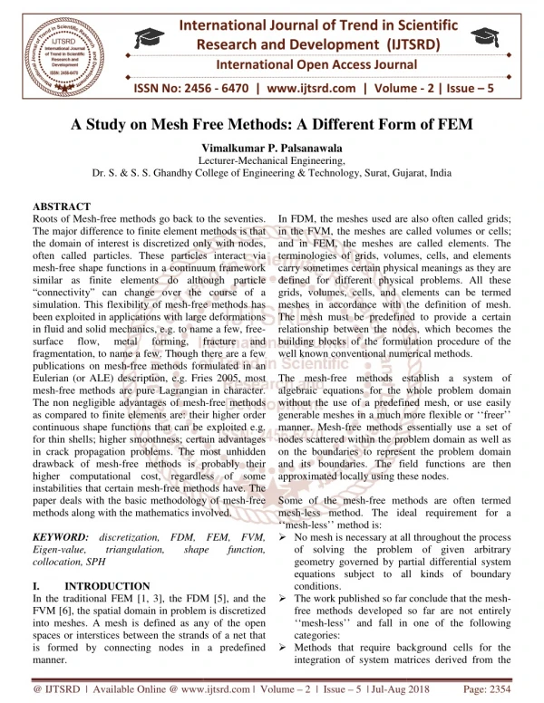
Roots of Mesh free methods go back to the seventies. The major difference to finite element methods is that the domain of interest is discretized only with nodes, often called particles. These particles interact via mesh free shape functions in a continuum framework similar as finite elements do although particle "connectivity can change over the course of a simulation. This flexibility of mesh free methods has been exploited in applications with large deformations in fluid and solid mechanics, e.g. to name a few, free surface flow, metal forming, fracture and fragmentation, to name a few. Though there are a few publications on mesh free methods formulated in an Eulerian or ALE description, e.g. Fries 2005, most mesh free methods are pure Lagrangian in character. The non negligible advantages of mesh free methods as compared to finite elements are their higher order continuous shape functions that can be exploited e.g. for thin shells higher smoothness certain advantages in crack propagation problems. The most unhidden drawback of mesh free methods is probably their higher computational cost, regardless of some instabilities that certain mesh free methods have. The paper deals with the basic methodology of mesh free methods along with the mathematics involved. Vimalkumar P. Palsanawala "A Study on Mesh Free Methods: A Different Form of FEM" Published in International Journal of Trend in Scientific Research and Development (ijtsrd), ISSN: 2456-6470, Volume-2 | Issue-5 , August 2018, URL: https://www.ijtsrd.com/papers/ijtsrd18314.pdf Paper URL: http://www.ijtsrd.com/engineering/mechanical-engineering/18314/a-study-on-mesh-free-methods-a-different-form-of-fem/vimalkumar-p-palsanawala<br>

E N D
International Research Research and Development (IJTSRD) International Open Access Journal n Mesh Free Methods: A Different Form of FEM Vimalkumar P. Palsanawala Lecturer-Mechanical Engineering, Ghandhy College of Engineering & Technology, Surat, Gujarat International Journal of Trend in Scientific Scientific (IJTSRD) International Open Access Journal ISSN No: 2456 ISSN No: 2456 - 6470 | www.ijtsrd.com | Volume 6470 | www.ijtsrd.com | Volume - 2 | Issue – 5 A Study on Mesh Free Methods: A Different Form of FEM n Mesh Free Methods: A Different Form of FEM Vimalkumar P. Palsanawala L Dr. S. & S. S. Ghandhy College Gujarat, India ABSTRACT Roots of Mesh-free methods go back to the seventies. The major difference to finite element methods is that the domain of interest is discretized only with nodes, often called particles. These particles interact via mesh-free shape functions in a continuum framework similar as finite elements do although particle “connectivity” can change over the course of a simulation. This flexibility of mesh-free methods has been exploited in applications with large deformations in fluid and solid mechanics, e.g. to name a few, free surface flow, metal fragmentation, to name a few. Though there are a few publications on mesh-free methods formulated in an Eulerian (or ALE) description, e.g. Fries 2005, most mesh-free methods are pure Lagrangian in character. The non negligible advantages of mesh as compared to finite elements are: their higher order continuous shape functions that can be exploited e.g. for thin shells; higher smoothness; certain adv in crack propagation problems. The most unhidden drawback of mesh-free methods is probably their higher computational cost, regardless of some instabilities that certain mesh-free methods have. The paper deals with the basic methodology of mesh methods along with the mathematics involved. KEYWORD: discretization, FDM, FEM, FVM, Eigen-value, triangulation, collocation, SPH I. INTRODUCTION In the traditional FEM [1, 3], the FDM [5], and the FVM [6], the spatial domain in problem is into meshes. A mesh is defined as any of the open spaces or interstices between the strands of a net that is formed by connecting nodes in a predefined manner. In FDM, the meshes used are also often called grids; in the FVM, the meshes are cal and in FEM, the meshes are called elements. The terminologies of grids, volumes, cells, and elements carry sometimes certain physical meanings as they are defined for different physical problems. All these grids, volumes, cells, and elements can be termed meshes in accordance with the definition of mesh. The mesh must be predefined to provide a certain relationship between the nodes, which becomes the building blocks of the formulation procedure of the well known conventional numerical The mesh-free methods establish a system of algebraic equations for the whole problem domain without the use of a predefined mesh, or use easily generable meshes in a much more flexible or ‘‘freer’’ manner. Mesh-free methods essentially use a se nodes scattered within the problem domain as well as on the boundaries to represent the problem domain and its boundaries. The field functions are then approximated locally using these nodes. Some of the mesh-free methods are often termed mesh-less method. The ideal requirement for a ‘‘mesh-less’’ method is: ?No mesh is necessary at all throughout the process of solving the problem of given arbitrary geometry governed by partial differential system equations subject to all kinds of boundary conditions. ?The work published so far conclude that the mesh free methods developed so far are not entirely ‘‘mesh-less’’ and fall in one of the following categories: ?Methods that require background cells for the integration of system matrices derived from the integration of system matrices derived from the free methods go back to the seventies. The major difference to finite element methods is that the domain of interest is discretized only with nodes, often called particles. These particles interact via free shape functions in a continuum framework similar as finite elements do although particle “connectivity” can change over the course of a In FDM, the meshes used are also often called grids; in the FVM, the meshes are called volumes or cells; and in FEM, the meshes are called elements. The terminologies of grids, volumes, cells, and elements carry sometimes certain physical meanings as they are defined for different physical problems. All these lements can be termed free methods has meshes in accordance with the definition of mesh. The mesh must be predefined to provide a certain relationship between the nodes, which becomes the building blocks of the formulation procedure of the well known conventional numerical methods. been exploited in applications with large deformations n fluid and solid mechanics, e.g. to name a few, free- surface flow, metal fragmentation, to name a few. Though there are a few free methods formulated in an Eulerian (or ALE) description, e.g. Fries 2005, most free methods are pure Lagrangian in character. The non negligible advantages of mesh-free methods as compared to finite elements are: their higher order continuous shape functions that can be exploited e.g. for thin shells; higher smoothness; certain advantages in crack propagation problems. The most unhidden free methods is probably their higher computational cost, regardless of some forming, forming, fracture fracture and and free methods establish a system of algebraic equations for the whole problem domain without the use of a predefined mesh, or use easily generable meshes in a much more flexible or ‘‘freer’’ free methods essentially use a set of nodes scattered within the problem domain as well as on the boundaries to represent the problem domain and its boundaries. The field functions are then approximated locally using these nodes. free methods have. The paper deals with the basic methodology of mesh-free methods along with the mathematics involved. free methods are often termed ethod. The ideal requirement for a No mesh is necessary at all throughout the process of solving the problem of given arbitrary geometry governed by partial differential system equations subject to all kinds of boundary discretization, FDM, FEM, FVM, triangulation, value, shape shape function, function, 3], the FDM [5], and the The work published so far conclude that the mesh- free methods developed so far are not entirely less’’ and fall in one of the following FVM [6], the spatial domain in problem is discretized into meshes. A mesh is defined as any of the open spaces or interstices between the strands of a net that is formed by connecting nodes in a predefined Methods that require background cells for the @ IJTSRD | Available Online @ www.ijtsrd.com @ IJTSRD | Available Online @ www.ijtsrd.com | Volume – 2 | Issue – 5 | Jul-Aug 2018 Aug 2018 Page: 2354
International Journal of Trend in Scientific Research and Development (IJTSRD) ISSN: 2456-6470 weak form over the problem domain. EFG methods may belong to this category. These methods are practical in many ways, as the creation of a background mesh is generally more feasible and can be much more easily automated using a triangular mesh for 2D domains and a tetrahedral mesh for 3D domains. ?Methods that require background cells locally for the integration of system matrices over the problem domain. These methods require only a local mesh and are easier to generate. ?Methods that do not require a mesh at all, but that are less stable and less accurate. Local point collocation methods using irregular grids may belong to this category. Automation of nodal selection and improving the stability of the solution are still some of the challenges in these kinds of methods. ?Particle methods that require a predefinition of particles for their volumes or masses. The algorithm will then carry out the analyses even if the problem domain undergoes extremely large deformation and separation. SPH methods belong to this category. This type of method suffers from problems in the imposition conditions. SPH simulates well the overall behaviors of certain class of problems such as highly nonlinear and momentum-driven problems. This loose definition of mesh-free method recognizes the fact: 1.Many mesh-free methods (often more robust, reliable, and effective ones) do use some kind of mesh, but the mesh is used in much more flexible and ‘‘freer’’ ways; 2.Most important motivation of developing mesh- free methods was to reduce the reliance on the use of ‘‘quality’’ meshes that are difficult or expensive to create for practical problems of complicated geometries II. THE IDEA OF MESH FREE METHODS: A close examination of the difficulties [1,3] associated with FEM pinpoints at the root of the problem: the heavy and rigid reliance on the use of quality elements that are the building blocks of FEM. A mesh with a predefined connectivity is required to form the elements that are used for both field variable interpolation and energy integration. As long as elements are used in such a rigid manner, the problems shall not be easy to solve. And, the idea of liminating or reducing the reliance on the elements and more flexible ways to make use of mesh has evolved. The concept of element-free, mesh-less, or mesh-free method was proposed, in which the domain of the problem is represented, ideally, only by a set of arbitrarily distributed nodes. The mesh-free methods have shown great potential for solving the difficult problems mentioned above. Triangular types of mesh that can be much more easily created automatically for complicated 2D and 3D domains, as shown in Figures 1 and 2. These types of triangular background cells are sufficient for necessary numerical operations in mesh-free methods. This provides flexibility in adding or deleting points/nodes whenever and wherever needed. For stress analysis of a solid domain, for example, there are often areas of stress concentration. One can relatively freely add nodes in the stress concentration area without worrying too much about their relationship with the other existing nodes. of boundary Figure - 1 a triangular mesh of elements or background cells for a complicated 2D domain In crack growth problems, nodes can be easily added around the crack tip to capture the stress concentration with desired accuracy. This nodal refinement can be moved with a propagation crack through background cells associated with the global geometry. Adaptive meshing for a large variety of problems, 2D or 3D, including linear and nonlinear, static and dynamic stress analysis, can be very effectively treated in mesh-free methods in a relatively simple manner. Because there is no need to create a quality mesh, and the nodes can be created by a computer in a much more automated manner, much of the time an engineer spending on conventional mesh generation can be saved. This can result in to substantial cost and time savings in modeling and simulation projects. @ IJTSRD | Available Online @ www.ijtsrd.com | Volume – 2 | Issue – 5 | Jul-Aug 2018 Page: 2355
International Journal of Trend in Scientific Research and Development (IJTSRD) ISSN International Journal of Trend in Scientific Research and Development (IJTSRD) ISSN International Journal of Trend in Scientific Research and Development (IJTSRD) ISSN: 2456-6470 (1) Where, Sn is the set of local nodes included in a ‘‘small local domain’’ of the point x, such a local domain is called support domain, and the set of local nodes are called support nodes ui is the nodal field variable at the i support domain ds is the vector that collects all the nodal field variables at these support nodes ɸi(x) is the shape function of the i all the support nodes in the support domain and is often called nodal shape function A support domain of a point x determines the number of nodes to be used to approximate the function value at x. A support domain can be weighted using functions that vanish on the boundary of the support domain, as shown in Figure- shapes and its dimension and shape can be different for different points of interest x, as shown in Figure The shapes most often used are circular or rectangular, or any shape to include desired supporting nodes. The concept of support domain works well if the nodal density does not vary too drastically in the problem domain. However, in solving practical problems, such as problems with stress singularity, the nodal density can vary drastically. The use of a support domain based on the current point of interest can lead to spatially biased selection of nodes for the construction of shape functions. is the set of local nodes included in a ‘‘small local domain’’ of the point x, such a local domain is called support domain, and the set of local nodes are called Figure - 2: a tetrahedral mesh of elements or background cells for a complicated 3D domain 2: a tetrahedral mesh of elements or is the nodal field variable at the ith node in the cated 3D domain III. BASIC TECHNIQUES FOR MESH METHODS: The general procedure and basic steps for mesh methods are presented here under through an example of structural problem. A.Basic steps: Step 1: Domain representation or discretization: The geometry of the solid or structure is first created in a CAE code or pre processor, and is triangulated to produce a set of triangular type cells with a set of nodes scattered in the problem domain and its boundary. Boundary conditions conditions are then specified for the model. The density of the nodes depends on the accuracy of the geometry, the accuracy requirement of the solution, and the limits of the computer resources available. The nodal distribution is usually not uniform and a denser distribution of nodes is often used in the area where the displacement gradient is larger. Because adaptive algorithms can be used in mesh-free methods, the density is eventually controlled automatically and adaptively in the code of the mesh-free method, we do not have to worry too much about the distribution quality of the initial nodes used in usual situations. In addition, as a mesh method, it should not demand too much for the pattern of nodal distribution. It should be workable withi reason for arbitrarily distributed nodes. Because the nodes shall carry the values of the field variables in a mesh-free formulation, they are often called field nodes. Step 2: Displacement interpolation: The field variable (say, a component of the displacement vector) u at any point at x=(x, y, z) within the problem domain is approximated or interpolated using the displacements at its nodes within the support domain of the point at x that is usually a quadrature point, i.e., BASIC TECHNIQUES FOR MESH-FREE is the vector that collects all the nodal field variables at these support nodes The general procedure and basic steps for mesh-free methods are presented here under through an example (x) is the shape function of the ith node created using all the support nodes in the support domain and is often called nodal shape function Step 1: Domain representation or discretization: geometry of the solid or structure is first created processor, and is triangulated to produce a set of triangular type cells with a set of nodes scattered in the problem domain and its boundary. Boundary conditions ns are then specified for the model. The density of the nodes depends on thepresentation accuracy of the geometry, the accuracy requirement of the solution, and the limits of the computer resources . The nodal distribution is usually not and a denser distribution of nodes is often used in the area where the displacement gradient is larger. Because adaptive algorithms can be used in free methods, the density is eventually controlled automatically and adaptively in the code of free method, we do not have to worry too much about the distribution quality of the initial nodes used in usual situations. In addition, as a mesh-free method, it should not demand too much for the pattern of nodal distribution. It should be workable within reason for arbitrarily distributed nodes. Because the nodes shall carry the values of the field variables in a free formulation, they are often called field A support domain of a point x determines the number of nodes to be used to approximate the function value at x. A support domain can be weighted using functions that vanish on the boundary of the support -3. It can have different and and loading loading shapes and its dimension and shape can be different for different points of interest x, as shown in Figure-4. The shapes most often used are circular or rectangular, or any shape to include desired supporting nodes. The concept of support domain ll if the nodal density does not vary too drastically in the problem domain. However, in solving practical problems, such as problems with stress singularity, the nodal density can vary drastically. The use of a support domain based on the interest can lead to spatially biased selection of nodes for the construction of shape The field variable (say, a component of the displacement vector) u at any point at x=(x, y, z) within the problem domain is approximated or interpolated using the displacements at its nodes within the support domain of the point at x that is Figure - -3 @ IJTSRD | Available Online @ www.ijtsrd.com @ IJTSRD | Available Online @ www.ijtsrd.com | Volume – 2 | Issue – 5 | Jul-Aug 2018 Aug 2018 Page: 2356
International Journal of Trend in Scientific Research and Development (IJTSRD) ISSN: 2456-6470 obtained. The strain and stress can then be retrieved using strain– displacement relations and constitutive equations. A standard linear algebraic equation solver, such as a Gauss elimination method, LU decomposition method, and iterative methods, can be used. 2.For free-vibration and buckling problems, Eigen values and corresponding eigenvectors can be obtained using the standard Eigen-value equation solvers. Some of the commonly used methods are the following: ?Jacobi’s method ?Given’s method ?The bisection method ?Inverse iteration ?Subspace iteration ?Lanczos method Figure - 4 In extreme situations, all the nodes used could be located on one side only, and the shape functions so constructed can result in serious error, due to extrapolation. To prevent this kind of problem, the concept of influence domain of a node should be used. The concept of influence domain is explained later on in the discussion. The interpolation, defined in Equation (1), is generally performed for all the components of all the field variables in the same support domain. For an example taking a 3D solid mechanics problem, the displacement is usually chosen as the field variable, and the displacement would have three components: displacements in the x- , y-, and z-directions. The same shape function is used for all three displacement components in the support domain of the same point. However, there are situations where different shape functions are used for different field variables. For example, for bending problems of beams, plates, and shells, it is advantageous to use different shape functions, respectively, for deflection overcoming the so-called shear and membrane locking issues. Step 3: Formation of system equations: The discrete equations of a mesh-free method can be formulated using the shape functions and weak or weakened-weak forms. These equations are often written in nodal matrix form and are assembled into the global system matrices for the entire problem domain. The procedures for forming system equations are different for different mesh-free methods. Step 4: Solving the global mesh-free equations: Solving the set of global mesh-free equations, we obtain solutions for different types of problems. 1.For static problems, the displacements at all the nodes in the entire problem domain are first 3.For dynamics problems, the time history of displacement, velocity, and acceleration are to be obtained. The following standard methods of solving dynamics equation systems can be used: ?The modal superposition method can be used for vibration types of problems and problems of far field response to low speed impact with many load cases. ?For problems with a single load or few loads, the direct integration method can be used, which uses the FDM for time stepping with implicit and explicit approaches. ?The implicit method is more efficient for relatively slow phenomena of vibration types of problems. ?The explicit method is more efficient for very fast phenomena, such as impact and explosion. For computational fluid dynamics problems, the discretized system equations are basically nonlinear, and one needs an additional iteration loop to obtain the results. B.Triangulation: Consider a d-dimensional problem domain of ΩЄ Rd bounded by Γ. By default, we speak of ‘‘open’’ domain that does not include the boundary of the domain. When we refer to a ‘‘closed’’ domain we will specifically use a box: Ω = Ω∩Γ. Triangulation is the most flexible way to create background triangular cells for mesh-free operations. The process can be almost fully automated for 2D and and rotation, in @ IJTSRD | Available Online @ www.ijtsrd.com | Volume – 2 | Issue – 5 | Jul-Aug 2018 Page: 2357
International Journal of Trend in Scientific Research and Development (IJTSRD) ISSN International Journal of Trend in Scientific Research and Development (IJTSRD) ISSN International Journal of Trend in Scientific Research and Development (IJTSRD) ISSN: 2456-6470 even 3D domains with complicated geometry. Therefore, it is used in most commercial pre processors using processes such as the widely used Delaunay triangulation. Concept of the Influence Domain: The support domain is defined as a domain in the vicinity of a point of interest xQ that can be, but does not have to be, at a node. It is used to include the nodes for shape function construction for x extended concept of the support domain means a particular way to select those nodes, not necessarily just by distance. The influence domain is defined as a domain that a node exerts an influence upon. It works well for very irregularly distributed nodes. Influence domains are defined for each node in the problem domain, and they can be different from node to node to represent the area of influence of the node, as shown in Figure 6. even 3D domains with complicated geometry. Therefore, it is used in most commercial pre sing processes such as the widely used (2) Where rI is the radius of the influence domain of node I nI is the number of surrounding triangular cells ai is the area of the ith cell αs is a constant scaling with the domain size The fact is that the dimension of the influence domain, which can be different from node to node, allows some nodes to have further others and prevents unbalanced nodal distribution for constructing shape functions. As shown in Figure - 6, node 1 is included for constructing shape functions for the point at point x but node 3 is not included, even though node 3 is closer to xQ compared with node 1. T-Schemes for Node Selection: Since the background cells are needed for integration for weak or weakened-weak form mesh background cells are often already made available. Therefore, it is natural to make the selection of supporting nodes for shape function construction. Background cells of triangular type generated by triangulation have been found most practical, robust, reliable, and efficient for local supporting node selection. Tria selection schemes are termed as T listed in Table 1. Table 1- T-Schemes for Node Selection Based on Triangular Background Cells Triangular Background Cells is the radius of the influence domain of node I is the number of surrounding triangular cells The support domain is defined as a domain in the that can be, but does not have to be, at a node. It is used to include the nodes for shape function construction for xQ. The extended concept of the support domain means a particular way to select those nodes, not necessarily is a constant scaling with the domain size The fact is that the dimension of the influence domain, which can be different from node to node, allows some nodes to have further influence than others and prevents unbalanced nodal distribution for The influence domain is defined as a domain that a works well for very irregularly distributed nodes. Influence domains are defined for each node in the problem domain, and they can be different from node to node to represent the area of influence of the node, as shown in Figure- 6, node 1 is included for constructing shape functions for the point at point xQ, but node 3 is not included, even though node 3 is compared with node 1. Schemes for Node Selection: Since the background cells are needed for integration weak form mesh-free methods, background cells are often already made available. Therefore, it is natural to make use of them also for the selection of supporting nodes for shape function construction. Background cells of triangular type generated by triangulation have been found most reliable, and efficient for local supporting node selection. Triangular cell-based node selection schemes are termed as T-schemes, and are Figure - 6: Influence domains of nodes e domains of nodes In constructing shape functions for point at xQ (marked with x), nodes whose influence domains covers x are to be used for construction of shape functions. For example, nodes 1 and 2 are included, but node 3 is not included. Node 1 has an influence radius of r1, and node 2 has an influence radius of r2, etc. The node will be involved in the shape function construction for any point that is within its influence domain. For example, in constructing the shape functions for the point marked with x at point xQ (see Figure and 2 will be used, but node 3 will not be used. The formula to compute the dimension of the influence domain of that node is Schemes for Node Selection Based on In constructing shape functions for point at xQ (marked with x), nodes whose influence domains covers x are to be used for construction of shape functions. For example, nodes 1 and 2 are included, , and node 2 has , etc. The node will be involved in the shape function construction for any point that is within its influence domain. For example, in constructing the shape functions for the point (see Figure - 6), nodes 1 and 2 will be used, but node 3 will not be used. The formula to compute the dimension of the @ IJTSRD | Available Online @ www.ijtsrd.com @ IJTSRD | Available Online @ www.ijtsrd.com | Volume – 2 | Issue – 5 | Jul-Aug 2018 Aug 2018 Page: 2358
International Journal of Trend in Scientific Research and Development (IJTSRD) ISSN International Journal of Trend in Scientific Research and Development (IJTSRD) ISSN International Journal of Trend in Scientific Research and Development (IJTSRD) ISSN: 2456-6470 In the definition of types of T-schemes, a home cell refers to the cell which hosts the point of interest (usually the quadrature sampling point). An interior home cell is a home cell that has no edge on the boundary of the problem domain and a boundary home cell is a home cell which has at least one edge on the boundary. A neighboring cell of a home cell refers to the cell which shares one edge with the home cell. Figure-7 shows the background triangular cells for 2D domain. The node selection is then performed as follows. T3-Scheme: In the T3-scheme, we simply select three nodes of the home cell of the point of interest. As illustrated in Fig-7 (a), no matter the point of interest x located in an interior home cell (cell i) or a boundary home cell (cell j), only the three nodes of the home cell (i j1_j3) are selected. T3-scheme is used only for creating linear PIM (Point Interpolation Method) shape functions by using polynomial basis functions. Note that the linear PIM shape functions so constructed are exactly the same as those in FEM using linear triangular elements. T4-Scheme: T4-scheme is the analogy of the T3-scheme, but of node selection for 3D domains with tetrahedral background cells. T6/3-Scheme: The T6/3-scheme selects six nodes to interpolate a point of interest located in an interior cell and three nodes for those located in boundary home cells. As illustrated in Figure-7 (b), when the point of interest xQ is located in an interior home cell (cell i), we select six nodes: three nodes of the home cell (i another three nodes located at the remote vertices of the three neighboring cells (i4_i6). When the point of interest at xQ is located in a boundary home cell (cell j), we select only three nodes of the home cell, i.e., j1_j3. T6/3-scheme was purposely devised for creating high order PIM shape functions, where interpolations are performed for the interior home cells and linear interpolations for boundary home cells. This scheme was first used in the NS It can not only successfully overcome the singular It can not only successfully overcome the singular schemes, a home cell the point of interest problem but also improve the efficiency of the problem but also improve the efficiency method. (usually the quadrature sampling point). An interior home cell is a home cell that has no edge on the boundary of the problem domain and a boundary home cell is a home cell which has at least one edge ll of a home cell refers to the cell which shares one edge with the home 7 shows the background triangular cells for 2D domain. The node selection is then performed as scheme, we simply select three nodes of the home cell of the point of interest. As illustrated in 7 (a), no matter the point of interest x located in an interior home cell (cell i) or a boundary home cell (cell j), only the three nodes of the home cell (i1_i3 or s used only for creating linear PIM (Point Interpolation Method) shape functions by using polynomial basis functions. Note that the linear PIM shape functions so constructed are exactly the same as those in FEM scheme, but of node selection for 3D domains with tetrahedral 7 (a) T3 Scheme, (b) T6/3-Scheme, (c)T6- , (d) & (e) T2L-Scheme Figure - 7 (a) T3 Scheme, (b) Scheme , (d) & (e) scheme selects six nodes to interpolate a point of interest located in an interior cell and three ated in boundary home cells. As 7 (b), when the point of interest is located in an interior home cell (cell i), we select six nodes: three nodes of the home cell (i1_i3) and another three nodes located at the remote vertices of T6-Scheme: Similar to T6/3-scheme, T6 Figure-7 (c), also selects six nodes for an interior home cell: three nodes of the home cell and vertexes at the remote vertices of the three neigh boring cells (i1_i6 for cell i). However, for a boundary cell (cell j), T6-scheme still selects six nodes: three nodes of the home cell (j1_j3 the neigh boring cells (j4 and j (j6) which is nearest to the centroid of the home cell excepting the five nodes that have been selected. T6-scheme is purposely devised for constructing radial PIM (RPIM) shape functions on considering both accuracy and efficiency. Dif scheme, this scheme selects six nodes for all home cells containing the point of interest. scheme, T6-scheme, as shown in 7 (c), also selects six nodes for an interior home cell: three nodes of the home cell and three vertexes at the remote vertices of the three neigh for cell i). However, for a boundary scheme still selects six nodes: three ). When the point of is located in a boundary home cell (cell j), we select only three nodes of the home cell, i.e., 3), two remote nodes of and j5), and one field node ) which is nearest to the centroid of the home cell excepting the five nodes that have been selected. scheme was purposely devised for creating high- order PIM shape functions, where quadratic interpolations are performed for the interior home cells and linear interpolations for boundary home cells. This scheme was first used in the NS-PIM [11]. scheme is purposely devised for constructing radial PIM (RPIM) shape functions on considering both accuracy and efficiency. Different from T6/3- scheme, this scheme selects six nodes for all home cells containing the point of interest. @ IJTSRD | Available Online @ www.ijtsrd.com @ IJTSRD | Available Online @ www.ijtsrd.com | Volume – 2 | Issue – 5 | Jul-Aug 2018 Aug 2018 Page: 2359
International Journal of Trend in Scientific Research and Development (IJTSRD) ISSN: 2456-6470 T2L-Scheme: T2L-scheme selects two layers of nodes to perform interpolation based on triangular meshes. As shown in Figure-7 (d) and (e), the first layer of nodes refers the three nodes of the home cell, and the second layer contains those nodes which are directly connected to the three nodes of the first layer. This scheme usually selects much more nodes than the T6-scheme and leads to more time consumption. We can use this scheme to create RPIM shape functions with high order of consistence and for extremely irregularly distributed nodes. Such RPIM shape functions can also be used for strong form mesh-free method methods where higher order of consistence is required. T2L-scheme can also be used for creating moving least squares (MLS) shape functions. REFERENCES 1.Lucy, L., A numerical approach to testing the fission hypothesis, Astronomical J., 82, 1013– 1024, 1977. 2.Gingold, R. A. and Monaghan, J. J., Smooth particle hydrodynamics: Theory and applications to non-spherical stars, Astronomical Soc., 181, 375–389, 1977. 3.Monaghan, J. J., Why particle methods work, Siam J. Sci. Stat. Comput., 3(4), 423–433, 1982. 4.Liu, M. B., Liu, G. R., and Zong, Z., An overview on smoothed particle hydrodynamics, Int. J. Comput. Methods, 5(1), 135–188, 2008. 5.Zhou, C. E., Liu, G. R., and Lou, K. Y., Three- dimensional penetration smoothed particle hydrodynamics, Int. J. Comput. Methods, 4(4), 671–691, 2007. 6.Liu, G. R. and Liu, M. B., Smoothed Particle Hydrodynamics—A Mesh free Practical Method, World Scientific, Singapore, 2003. 7.Liu, G. R., Zhang, J., and Lam, K. Y., A gradient smoothing method (GSM) with directional correction for solid mechanics problems, Comput. Mech., 41, 457–472, 2008. 8.Liu, G. R. and Xu, G. X., A gradient smoothing method (GSM) for fluid dynamics problems, Int. J. Numerical Methods Fluids, 56(10), 1101–1133, 2008. 9.Xu, G. X., Liu, G. R., and Lee, K. H., Application of gradient smoothing method (GSM) for steady and unsteady incompressible flow problems using irregular triangles, Submitted to Int. J. Numerical Methods Fluids, 2008. 10.Xu, G. X. and Liu G. R., An adaptive gradient smoothing method (GSM) for fluid dynamics problems, Int. J. Numerical Methods Fluids, accepted, 2008. 11.Liu, G. R., Liu, M. B., and Lam, K. Y., A general approach for constructing smoothing functions for meshfree methods, International Conference on Computing in Civil and Building Engineering, Taipei, China, April 3– 5, 2002, pp. 431–436. 12.Liu, W. K., Adee, J., and Jun, S., Reproducing kernel and wavelet particle methods for elastic and plastic problems, in Advanced Computational Methods for Material Modeling, Benson, D. J., ed., AMD 180=PVP 268 ASME, New Orleans, LA, 1993, pp. 175–190. 13.Liu, W. K., Jun, S., and Zhang, Y., Reproducing kernel particle methods, Int. J. Numerical Methods Fluids, 20, 1081–1106, 1995. 14.Liu, W. K., Chen, Y., Chang, C. T., and Belytschko, T., Advances in multiple scale kernel particle methods, Comput. Mech., 18, 73–111, 1996. 15.Liu, W. K., Jun, S., Sihling, D. T., Chen, Y. J., and Hao, W., Multiresolution reproducing kernel particle method for computational fluid dynamics, Int. J. Numerical Methods Fluids, 24, 1–25, 1997. 16.Liu, W. K., Jun, S., Sihling, D. T., Chen, Y. J., and Hao, W., Multi resolution reproducing kernel particle method for computational fluid dynamics, Int. J. Numerical Methods Fluids, 24, 1391–1415, 1997. 17.Liu, W. K., Li, S. F., and Belytschko, T., Moving least-square reproducing kernel methods: I Methodology and convergence, Comput. Methods Appl. Mech. Eng., 143, 113–154, 1997. 18.Chen, J. S., Pan, C., Wu, C. T., and Liu, W. K., Reproducing kernel particle methods for large deformation analysis of nonlinear structures, Comput. Methods Appl. Mech. Eng., 139, 195– 228, 1996. 19.Uras, R. A., Chang, C. T., Chen, Y., and Liu, W. K., Multi resolution reproducing kernel particle methods in acoustics, J. Comput. Acoust., 5(1), 71–94, 1997. presented at Ninth Mon. Notices R. simulation using @ IJTSRD | Available Online @ www.ijtsrd.com | Volume – 2 | Issue – 5 | Jul-Aug 2018 Page: 2360
International Journal of Trend in Scientific Research and Development (IJTSRD) ISSN: 2456-6470 20.Lancaster, P. and Salkauskas, K., Surfaces generated by moving least squares methods, Math. Comput., 37, 141–158, 1981. 21.Cleveland, W. S., Visualizing Data, AT&T Bell Laboratories, Murray Hill, NJ, 1993. 22.Nayroles, B., Touzot, G., and Villon, P., Generalizing the finite element method: Diffuse approximation and diffuse elements, Comput. Mech., 10, 307–318, 1992. 23.Belytschko, T., Lu, Y. Y., and Gu, L., Element- free Galerkin methods, Int. J. Numerical Methods Eng., 37, 229–256, 1994. 24.Krongauz, Y. and Belytschko, T., Enforcement of essential boundary conditions in mesh less approximations using finite elements, Comput. Methods Appl. Mech. Eng., 131(1–2), 133–145, 1996. 25.Belytschko, T., Gu, L., and Lu, Y. Y., Fracture and crack growth by element free Galerkin methods, Model. Simulations Mater. Sci. Eng., 2, 519–534, 1994. @ IJTSRD | Available Online @ www.ijtsrd.com | Volume – 2 | Issue – 5 | Jul-Aug 2018 Page: 2361