Download
1 / 1
10 likes | 151 Views
Two Possible Neutralization Methods. Conclusions. Motivation. Results to Date. The Nanoparticle Field Extraction Thruster (NanoFET) is an electric propulsion device that charges and accelerates nanoparticles using electrostatic fields and MEMS structures.

E N D
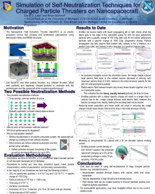
Two Possible Neutralization Methods Conclusions Motivation Results to Date • The Nanoparticle Field Extraction Thruster (NanoFET) is an electric propulsion device that charges and accelerates nanoparticles using electrostatic fields and MEMS structures. • Can NanoFET and other particle thrusters, e.g. colloidal thrusters, utilize both positively and negatively charged particles to neutralize both the emitted beam and the spacecraft while maintaining performance? • Two possible neutralization methods • Time-varying, common emitter structure • Spatially separated, constant steady-state emission • How do each of the emission methods behave? • Will thrust performance be degraded? • Why is neutralization needed? • Without neutralization in an electric propulsion system, the spacecraft will charge up creating a virtual cathode situation. • Other options are hollow cathode neutralizers and field • emitter array cathodes. • Hollow cathodes increase complexity of the system • as well as decrease efficiency by up to 20%. • Care must be taken in using self-neutralization of large charged particle thruster, e.g. colloidal thrusters. • Neutralization possible through beams with narrow width and close separation. • Velocity degradation at high thrust/current density levels. • High electric field can be created external to thruster between positive and negative particle populations. • For nanosatellite applications, may have negligible effects due to low current density levels. • Emitted net neutral beam with beam propagating left to right shown when the beam gets to the edge of the simulation space for 200 nm solid polystyrene particles with a specific charge of 100 C/kg (left) and 50 nm hollow polystyrene particles with a specific charge of 1000 C/kg. Diagnostics shown: Particle propagation (top left), electric field (bottom left), velocity in the y direction vs x position (top right), and velocity in the x direction vs x position (bottom right). • As particles propagate across the simulation space, the image charge induced axial electric field local to the emitter causes decrease in velocity, with maximum velocity drop of 0.22% relative to the initial emission velocity for the 200 nm solid polystyrene particle. • Radial electric field between beams only slowly draws beams together over 0.2 m of simulation space. • This indicates that the heavy, equally massed particles are slow to move. • Emitting particles with a higher specific charge will result in a larger drop in velocity due to the image charge induced axial electric field; however, the beams converge more readily, making the resulting beam more neutral. • Reducing beam separation and beam width will result in reducing the image charge induced axial electric field and the drop in the initial emission velocity. • Modeling an unneutralized 3U cubesat with a 30 cm diameter sphere emitting current. • Emitting a beam current density of • 9.67 mA/cm2 results in the simulated • spacecraft charging up to 5% of the • accelerating voltage in under 10 μs, • requiring ~100 kHz pulse. Evaluation Methodology • Simulations are done in XOOPIC, a 2.5 dimensional object-oriented particle-in-cell simulator developed at UC-Berkeley. • Parameters to control are: time step, simulation space, mesh, particle characteristics, emitter characteristics, and boundary characteristics • In the majority of our simulations we have kept the following constant: • 200 nm polystyrene particles -> 4.4*10-18 kg and 7.32*10-16 C -> specific charge of ~100 C/kg • Exhaust velocity of 104 m/s -> 1000 s Isp • Time step of 2*10-12 s • Cartesian coordinates • X-direction of 0.2 m, Y-direction of 0.15 m, 30 mesh cells per direction • Current density of 9.67 mA/cm2 Simulation of Self-Neutralization Techniques for Charged Particle Thrusters on Nanospacecraft X vs Y Particle Propagation Resulting Velocity (VY vs X) in m/s X vs Y Particle Propagation Resulting Velocity (VY vs X) in m/s David C. Liaw1 and Brian Gilchrist2 1 EECS/RadLab at the University of Michigan, 2 EECS/AOSS at the University of Michigan Sponsored by AFRL/AFOSR, Dr. Dan Brown and the Michigan Center for Excellence in Electric Propulsion Electric Field Resulting Velocity (VX vs X) in m/s Electric Field Resulting Velocity (VX vs X) in m/s Conceptual Nanospaceraft with NanoFET E_x Positive Emission Beam Separation E_x Negative Emission E_x Positive Emission Beam Width Beam Width E_x Negative Emission